Csl tray additional hardware, Csl tray additional hardware -37 – StorageTek 9840 User Manual
Page 87
95741
Sixth Edition
3-37
Rack
CSL Tray Additional Hardware
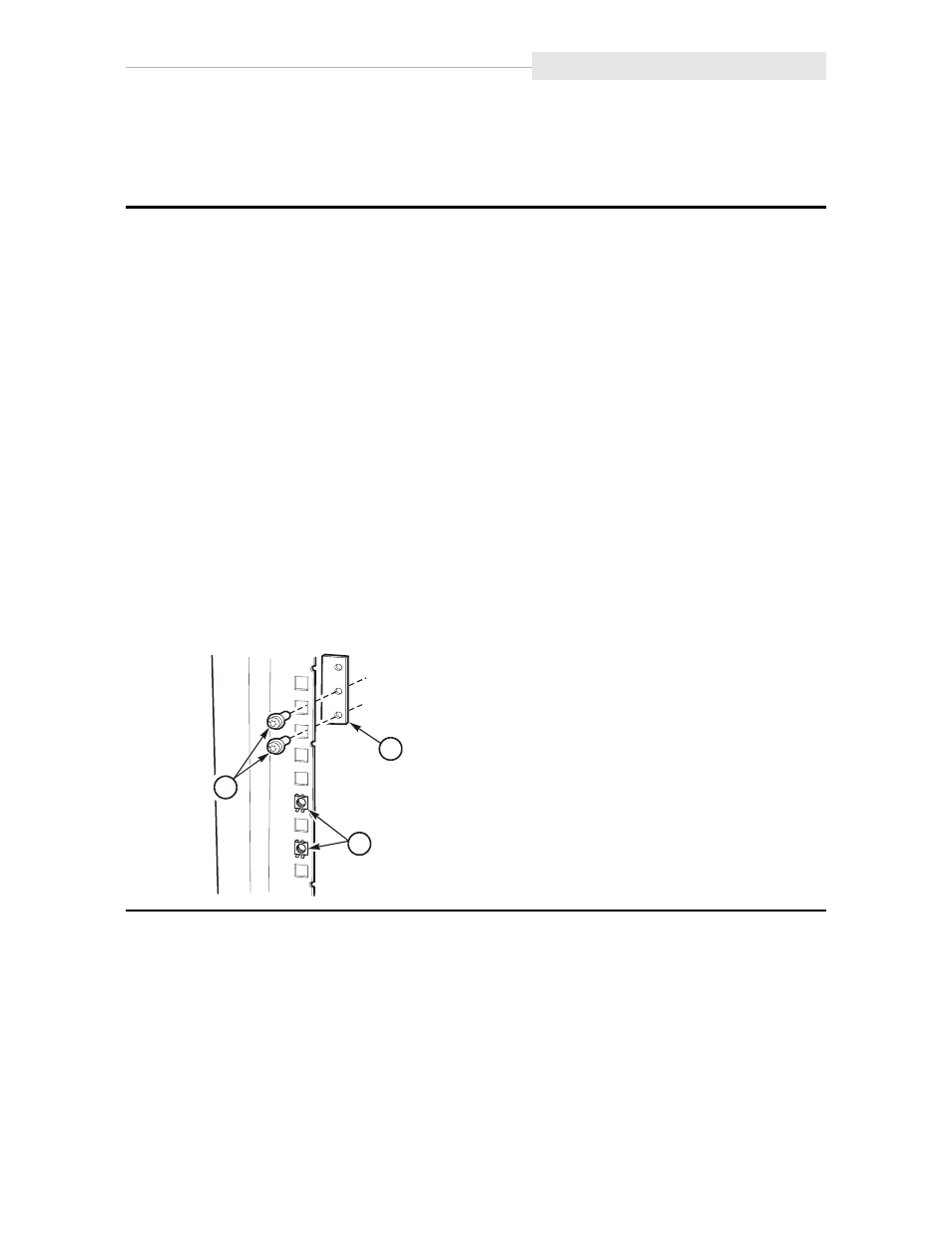
You will be removing a rack filler plate to enable installation of a CSL tray.
1. Remove the decorative cover from the filler plate.
2. Remove the screws from the filler plate and remove the plate.
Note: The filler plate uses holes 3 and 10.
3. Reposition the captive nuts to holes 6 and 8.
Note: Make sure to identify the starting point for numbering holes. You need to start
below the lowest point in the tray mounting plate. If you start immediately below
the slide-rail of the drive tray, the nut plate will be mounted too high.
4. At the front of the cabinet, insert a nut plate into holes 2 and 3.
Note: Only turn the screws until a few threads are in the nut plate. In a later step, the
slide-rail assembly will be inserted between the nut plate and the frame member.
5. At the rear of the cabinet, insert a nut plate into holes 2 and 3.
6. Install slide rails by attaching them at holes 10 and 11.
7. Repeat Steps 1 through Step 6 for each additional CSL you will be installing.
8. Proceed to
“Rack-mountable Tray” on page 3-38
if you will not be installing drive trays.
1. Screws (2)
2. Nut plate
3. Captive nuts
C53680
1
2
3