114 serial preload sequence, Ed in, Serial preload – Intel 21555 User Manual
Page 180
180
21555 Non-Transparent PCI-to-PCI Bridge User Manual
List of Registers
3
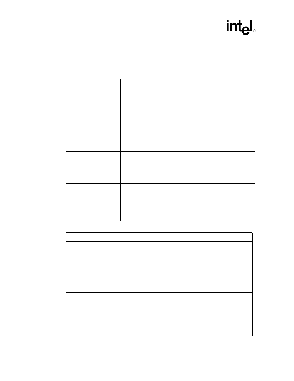
s_clk_o
Enable
R
Indicates whether s_clk_o is enabled, determined by sampling pr_ad[5]
during reset.
•
When 0, signal pr_ad[5] was sampled low, causing s_clk_o to be
disabled.
•
When 1, signal pr_ad[5] was sampled high, causing s_clk_o to be
enabled.
4
Secondary
Central
Function
Enable
R
Indicates whether secondary bus central functions are enabled, determined
by sampling pr_ad[6] during reset.
•
When 0, signal pr_ad[6] was sampled low, causing secondary central
functions to be enabled.
•
When 1, signal pr_ad[6] was sampled high, causing secondary central
functions to be disabled.
5
Arbiter
Enable
R
Indicates whether the secondary bus arbiter is enabled, determined by
sampling pr_ad[7] during reset.
•
When 0, signal pr_ad[7] was sampled low, causing the secondary bus
arbiter to be disabled.
•
When 1, signal pr_ad[7] was sampled high, causing the secondary bus
arbiter to be enabled.
6
Primary
64
-
Bit
Extension
R
Indicates whether the primary bus 64
-
bit extension is enabled.
•
When 0, the primary bus 64
-
bit extension is disabled.
•
When 1, the primary bus 64
-
bit extension is enabled.
7
Secondary
64
-
Bit
Extension
R
Indicates whether the secondary bus 64
-
bit extension is enabled.
•
When 0, the secondary bus 64
-
bit extension is disabled.
•
When 1, the secondary bus 64
-
bit extension is enabled.
Table 114. Serial Preload Sequence (Sheet 1 of 3)
Not all of the bits in the sequence are used. Bits that are not used must be 0 (zero)
Byte
offset
Description
00h
Register preload control
•
Bits [7:6] must read as 10b to enable the register preload; otherwise, the serial ROM read
is terminated and registers remain at their reset values.
•
Bits [5:0] are reserved and must be 0.
01h
00000000b (Reserved)
02h
00000000b (Reserved)
03h
00000000b (Reserved)
04h
Primary Programming Interface
05h
Primary Sub
-
Class Code
06h
Primary Base Class Code
07h
Subsystem Vendor ID [7:0]
08h
Subsystem Vendor ID [15:8]
Table 113. Mode Setting Configuration Register (Sheet 2 of 2)
This register reflects the various mode settings selected by strapping the pr_ad pins, as well as whether the
64-bit extension is enabled.
•
Primary byte offset: D6h
•
Secondary byte offset: D6h
Bit
Name
R/W
Description