Intel 21555 User Manual
Page 133
21555 Non-Transparent PCI-to-PCI Bridge User Manual
133
List of Registers
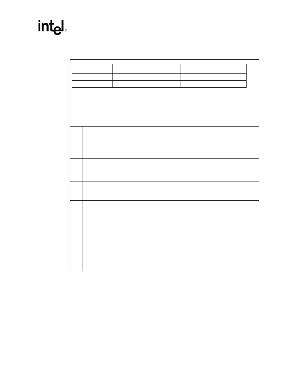
Table 37. Downstream I/O or Memory 1 and Upstream I/O or Memory 0 BAR
Bit
Name
R/W
Description
0
Space Indicator
R
•
When a 0, this BAR is disabled or memory space is requested
memory space.
•
When a one (1), I/O space is requested.
•
Reset value is 0
2:1
Type
R
•
When all zeros (0s), I/O space is requested.
•
When non
-
zero, memory space is requested and the number
equals the size and location of this address range.
•
Reset value is 00b
3
Prefetchable
R
•
When 0, requesting I/O or nonprefetchable memory.
•
When 1, requesting prefetchable memory space.
•
Reset value is 0
5:4
—
R
Returns zeros (0s).
31:6
Base Address
R/W
Indicate the size of the requested address range and set the base
address of the range.
The corresponding setup register determine the function of the
corresponding bit in this register.
•
When a 0, the same bit in this register is a read
-
only bit and always
return 0 when read.
•
When a one (1), the same bit in this register is writable and return
the value last written when read.
This BAR is disabled by writing a 0 to bit [31] of the setup register. The
minimum size for an I/O address range is 64 bytes and for a memory
range is 4 KB. The maximum size is 2 GB.
•
Reset value is This register is disabled (read only as 0).
These registers define forwarding address ranges for downstream or upstream I/O or memory transactions.
After reset, they are disabled and return all zeros when read.
This register can request a 64, 128, or 256 bytes I/O space. Hardware does not restrict larger I/O windows or
4 KB to 2 GB. To configure a space use serial preloading or program the Downstream I/O or Memory 1 Setup
register or Upstream I/O or Memory 0 Setup register.
Access of the setup registers must be through the local processor before the Primary Lockout Reset Value bit is
cleared.
Offsets
Downstream I/O or Memory 1 BAR
Upstream I/O or Memory 0 BAR
Primary byte
1B:18h
5B:58h
Secondary byte
5B:58h
1B:18h