1 host interface, 2 dedicated debug monitor memory, Host interface -11 – Motorola MC68VZ328 User Manual
Page 303: Dedicated debug monitor memory -11, Figure 16-2, Typical emulator design example -11
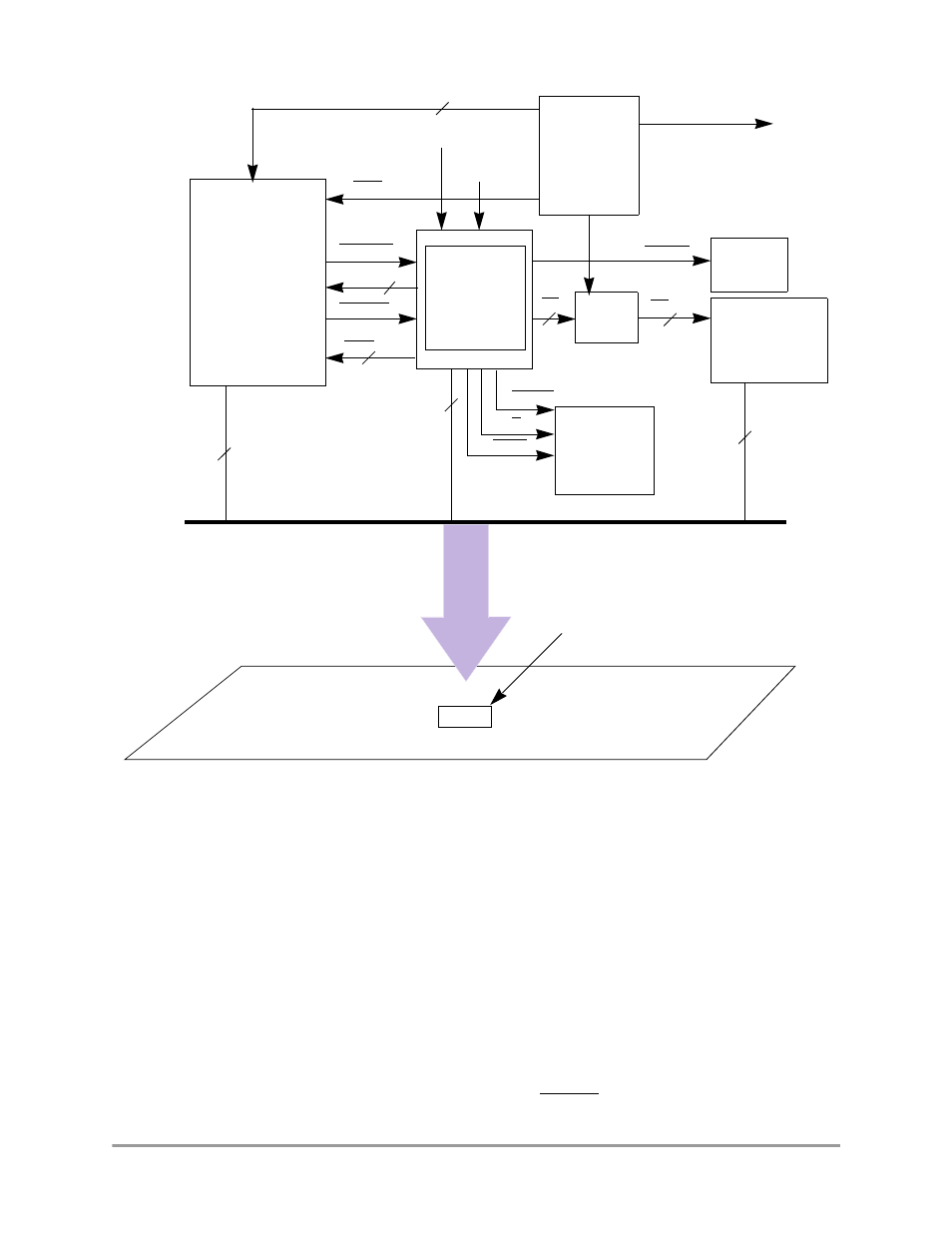
Typical Design Programming Example
In-Circuit Emulation
16-11
Figure 16-2. Typical Emulator Design Example
16.3.1
Host Interface
The host interface can be a processor-based or state-machine-based circuit that is used to coordinate the
activities between the emulation processor and the PC host. The interface can be an RS-232 or printer
parallel I/O. The interface runs on the PC, and it will translate its requests to low-level commands and send
them to the emulator’s controller if there is one.
16.3.2
Dedicated Debug Monitor Memory
When a breakpoint is matched, the CPU must report its status and grab the necessary contents, such as
internal registers, in the system. This information is then transmitted to the host control processor to be
translated before it is passed to the interface on the PC. The monitor program is located in ROM at
0xFFFC0000–0xFFFCFFFF and is enabled or disabled by the EMUCS signal.
Host
Control
PC
Address
Comparator
FPGA for
MAP
Emulation
Memory
4M Maximum
Debug
EMUCS
A[23:0]
CSxx
MOCLK
BUSW
EMUIRQ
D[15:0]
Select/control
Select/Control
MC68VZ328
CPU
More
Hardware
Breakpoint
Expansion
(Optional)
EMUBRK
CS
CS
ROM
Solder-on
Emulator Pod
Target Board
Footprint
(Optional)
FPGA
Optional
Trace
Module
P/D
CLKO
DTACK
3.3 V / 5 V Buffer
CSxx
D[15:0]
D[15:0]
Bus
M
C68VZ328