4 port k pull-up/pull-down enable register, 5 port k select register, Port k pull-up/pull-down enable register -36 – Motorola MC68VZ328 User Manual
Page 206: Port k select register -36, Table 10-49, Table 10-50, Port k select register description -36, Pksel port k select register 0x(ff)fff443
10-36
MC68VZ328 User’s Manual
Programming Model
When bit 0 is set as DATA_READY, it can be used in master mode to signal the SPI master to clock out
data. PWMO2 is an output signal from the PWM 2 module. If this pin is configured as this dedicated
function and PKDIR0 is set to 1, the PWMO2 signal is selected. If PKDIR0 is 0, DATA_READY is
selected. This pin defaults to Port K data bit 0, GPIO input, pulled high.
When selected bit 1 (RW) is connected to the 68000 CPU Read/Write signal, this pin defaults to Port K
bit 1, GPIO input, pulled high.
The remaining bits are involved with bus control. See Section 2.6, “Bus Control Signals,” on page 2-6 for
more detailed information.
10.4.10.4
Port K Pull-up/Pull-down Enable Register
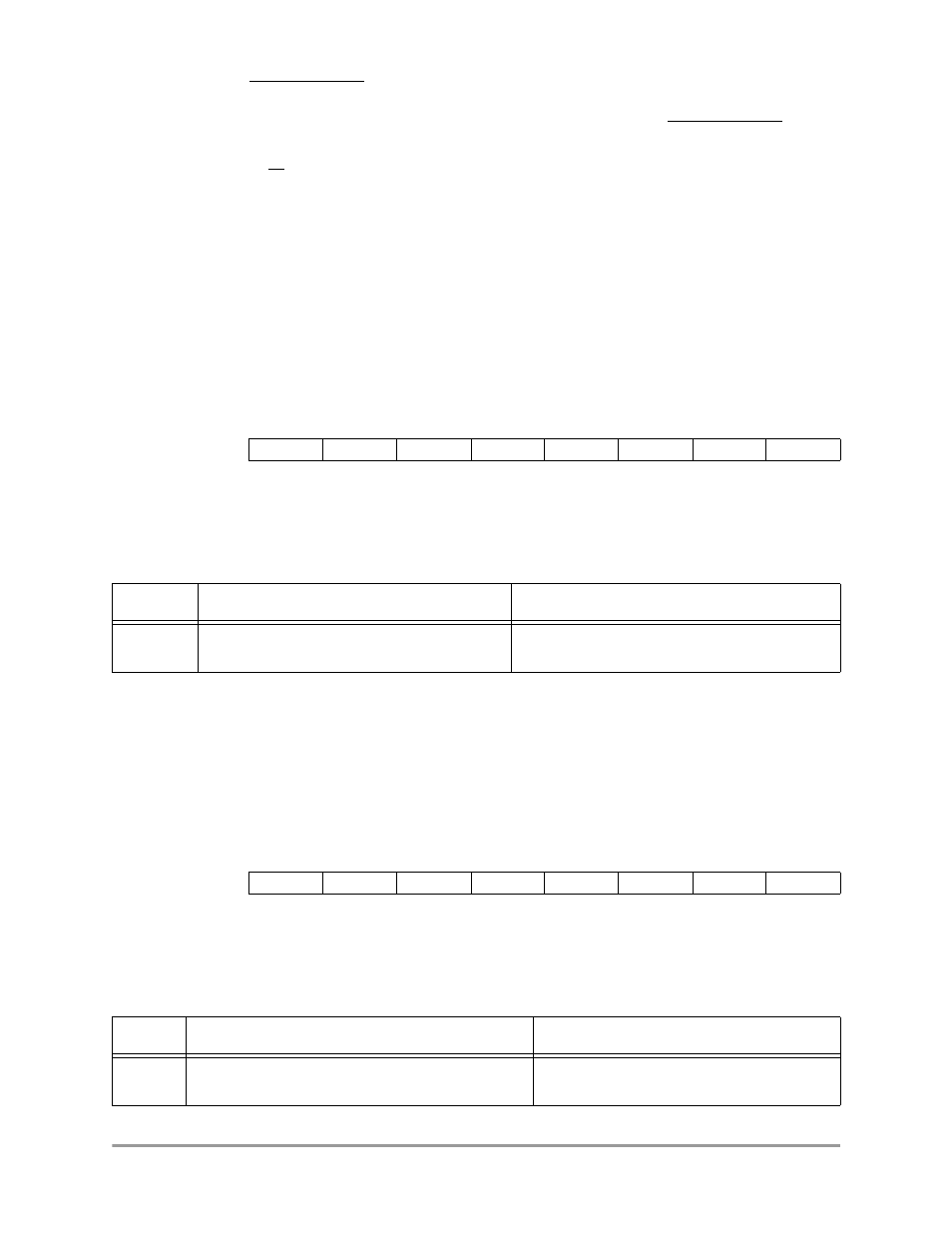
The pull-up/pull-down enable register (PKPUEN) controls the pull-up and the pull-down resistors for each
line in Port K. The settings for the PKPUEN register bit positions are shown in Table 10-49.
PKPUEN
Port K Pull-up/Pull-down Enable Register
0x(FF)FFF442
10.4.10.5
Port K Select Register
The select register (PKSEL) determines if a bit position in the data register (PKDATA) is assigned as a
GPIO or to a dedicated I/O function. The settings for the PKSEL register bit positions are shown in
Table 10-50.
PKSEL
Port K Select Register
0x(FF)FFF443
BIT 7
6
5
4
3
2
1
BIT 0
PD7
PD6
PD5
PD4
PU3
PU2
PU1
PU0
TYPE
rw
rw
rw
rw
rw
rw
rw
rw
RESET
1
1
1
1
1
1
1
1
0xFF
Table 10-49. Port K Pull-up/Pull-down Enable Register Description
Name Description
Setting
PUx
Bits 7–0
Pull-up/Pull-down Enable—These bits enable
the pull-up and pull-down resistors on the port.
0 = Pull-up and pull-down resistors are disabled
1 = Pull-up and pull-down resistors are enabled
BIT 7
6
5
4
3
2
1
BIT 0
SEL7
SEL6
SEL5
SEL4
SEL3
SEL2
SEL1
SEL0
TYPE
rw
rw
rw
rw
rw
rw
rw
rw
RESET
1
1
1
1
1
1
1
1
0xFF
Table 10-50. Port K Select Register Description
Name Description
Setting
SELx
Bits 7–0
Select—These bits select whether the internal chip
function or I/O port signals are connected to the pins.
0 = The dedicated function pins are connected.
1 = The I/O port function pins are connected.