Motorola MC68VZ328 User Manual
Page 164
9-14
MC68VZ328 User’s Manual
Programming Model
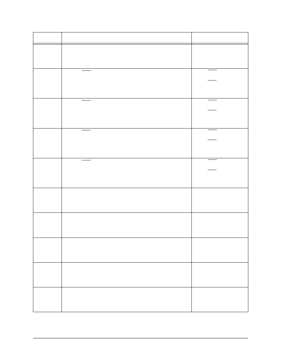
UART2
Bit 12
UART 2 Interrupt Request—When set, this bit indicates that the
UART 2 module needs service. The interrupt level is configurable
from level 1 to level 6. See Section 9.6.6, “Interrupt Level Register,”
for more details.
0 = No UART 2 interrupt
request is pending.
1 = UART 2 interrupt
request is pending.
INT3
Bit 11
External INT3 Interrupt—This bit, when set, indicates that a level 4
interrupt has occurred. It is usually for a keyboard interface. When it
is programmed as edge-triggered, it can only be cleared by writing a
1 to the port D register. See Section 10.4.5, “Port D Registers,” on
page 10-16 for details.
0 = No INT3 interrupt is
pending.
1 = An INT3 interrupt is
pending.
INT2
Bit 10
External INT2 Interrupt—This bit, when set, indicates that a level 4
interrupt has occurred. It is usually for a keyboard interface. When it
is programmed as edge-triggered, it can only be cleared by writing a
1 to the port D register. See Section 10.4.5, “Port D Registers,” on
page 10-16 for details.
0 = No INT2 interrupt is
pending.
1 = An INT2 interrupt is
pending.
INT1
Bit 9
External INT1 Interrupt—This bit, when set, indicates that a level 4
interrupt has occurred. It is usually for a keyboard interface. When it
is programmed as edge-triggered, it can only be cleared by writing a
1 to the port D register. See Section 10.4.5, “Port D Registers,” on
page 10-16 for details.
0 = No INT1 interrupt is
pending.
1 = An INT1 interrupt is
pending.
INT0
Bit 8
External INT0 Interrupt—This bit, when set, indicates that a level 4
interrupt has occurred. It is usually for a keyboard interface. When it
is programmed as edge-triggered, it can only be cleared by writing a
1 to the port D register. See Section 10.4.5, “Port D Registers,” on
page 10-16 for details.
0 = No INT0 interrupt is
pending.
1 = An INT0 interrupt is
pending.
PWM1
Bit 7
Pulse-Width Modulator (PWM 1) Interrupt—This bit, when set,
indicates that there is a level 6 interrupt event from PWM unit 1
pending.
0 = No PWM 1 interrupt is
pending.
1 = A PWM 1 interrupt is
pending.
KB
Bit 6
Keyboard Interrupt Request—This bit, when set, indicates that
there is a level 4 interrupt event from a keyboard pending.
0 = No keyboard interrupt is
pending.
1 = A keyboard interrupt is
pending.
TMR2
Bit 5
Timer 2 Interrupt Status—This bit indicates that a timer 2 event has
occurred. This is a level 4 interrupt.
0 = No timer 2 event
occurred.
1 = A timer 2 event has
occurred.
RTC
Bit 4
Real-Time Clock Interrupt Request—This bit, when set, indicates
that there is a level 4 interrupt event from the real-time clock that is
pending.
0 = No real-time clock
interrupt is pending.
1 = A real-time clock
interrupt is pending.
WDT
Bit 3
Watchdog Timer Interrupt Request—This bit indicates that a
watchdog timer interrupt is pending. This is a level 4 interrupt.
0 = No watchdog timer
interrupt is pending.
1 = A watchdog timer
interrupt is pending.
Table 9-6. Interrupt Status Register Description (Continued)
Name
Description
Settings