3 port m dedicated i/o functions, 4 port m pull-up/pull-down enable register, Port m dedicated i/o functions -39 – Motorola MC68VZ328 User Manual
Page 209: Port m pull-up/pull-down enable register -39, Table 10-53, Port m dedicated i/o function assignments -39, Table 10-54
Programming Model
I/O Ports
10-39
10.4.11.3
Port M Dedicated I/O Functions
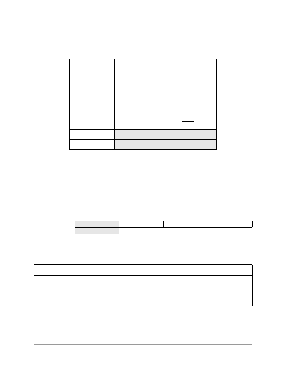
The six PMDATA lines are multiplexed with the dedicated I/O signals whose assignments are shown in
Table 10-53.
All of the dedicated I/O functions are involved in the operation of the DRAM controller. See Chapter 7,
“DRAM Controller,” for more details.
10.4.11.4
Port M Pull-up/Pull-down Enable Register
The pull-up/pull-down enable register (PMPUEN) controls the pull-up and pull-down resistors for each
line in Port M. The settings for the PMPUEN register bit positions are shown in Table 10-54.
PMPUEN
Port M Pull-up/Pull-down Enable Register
0x(FF)FFF44A
Table 10-53. Port M Dedicated I/O Function Assignments
Bit
GPIO Function
Dedicated I/O Function
0
Data bit 0
SDCLK
1
Data bit 1
SDCE
2
Data bit 2
DQMH
3
Data bit 3
DQML
4
Data bit 4
SDA10
5
Data bit 5
DMOE
6
7
BIT 7
6
5
4
3
2
1
BIT 0
PU5
PD4
PD3
PD2
PD1
PD0
TYPE
rw
rw
rw
rw
rw
rw
RESET
0
0
1
1
1
1
1
1
0x3F
Table 10-54. Port M Pull-up/Pull-down Enable Register Description
Name Description
Setting
Reserved
Bits
7–6
Reserved
These bits are reserved and should be set to 0.
PUx
Bits 5–0
Pull-up/Pull-down Enable—These bits enable
the pull-up and pull-down resistors on the port.
0 = Pull-up and pull-down resistors are disabled
1 = Pull-up and pull-down resistors are enabled