FARGO electronic DTC300 User Manual
Page 312
RESTRICTED USE ONLY
Fargo Electronics, Inc.
DTC400/DTC300/DTC300M Card Printer Service Manual (Rev. 1.3)
8-58
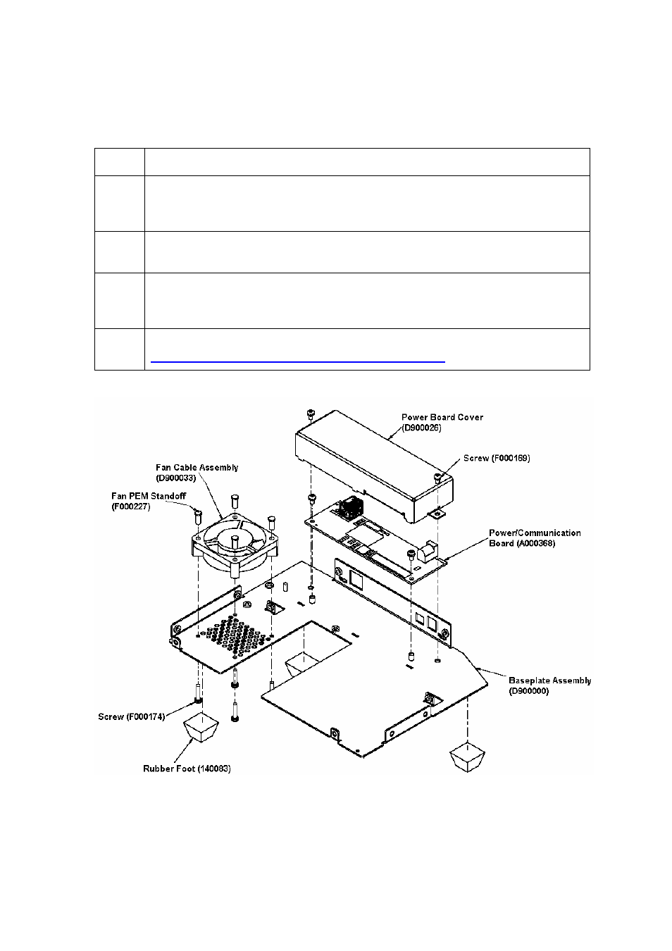
Replacing the Power/Communication Board (A000368) (continued)
Steps Procedure
7
Use a Torx T-10 screwdriver to remove the two (2) screws (F000169) that
secure the Power/Communication Board Cover (D900026) to the Printer
Baseplate (D900000). See below.
8
Disconnect the Communication Ribbon Wire (D900034) from the J3 Power
Board connection.
9
Use a Torx T-10 screwdriver to remove the two (2) screws (F000169) that
secure the Printer Power/Communication Board (A000368) to the Printer
Baseplate. See below.
10
Remove and replace the Power/Communication Board (A000368). See
Replacing the Power/Communication Board (A000368)
.