Processor board assembly (front view), Figure 3-13, Figure 3-14 – HP INTEGRITY RX3600 User Manual
Page 77
17. Replace the memory carrier assembly cover and latch the top cover release lever closed. See
“Replacing the Memory Carrier Assembly Cover” (page 58)
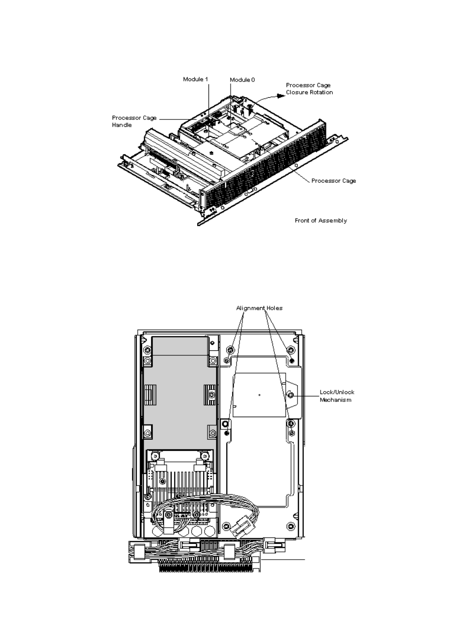
Figure 3-13 Processor Board Assembly (Front View)
shows the power connectors, the processor lock / unlock mechanism location and
the alignment holes. One processor is installed in the illustration.
Figure 3-14 Processor Alignment Holes and Lock/Unlock Mechanism
Installing Additional Components
77
See also other documents in the category HP Computer Accessories:
- Surge Protectors (2 pages)
- EXPANSION BASE 344524-001 (74 pages)
- DESKJET 712C (22 pages)
- 224M (166 pages)
- 6308M-SX (8 pages)
- 2103R-CSDI (92 pages)
- Webcam (3 pages)
- 4100GL (228 pages)
- XP10000 (82 pages)
- 326431 (2 pages)
- 2520G-POE (101 pages)
- 5300 (164 pages)
- Elite Autofocus Webcam (20 pages)
- 5400zl Series (16 pages)
- 2610 (364 pages)
- 8200ZL (314 pages)
- DV6 (130 pages)
- HD-3100 (2 pages)
- 9308M (27 pages)
- 6108 (300 pages)
- 2600 Series (306 pages)
- DC149B (3 pages)
- 2600-PWR (418 pages)
- 3110 (22 pages)
- 6400CL (84 pages)
- INSIGHT DYNAMICS T8671-91017 (54 pages)
- 4000M (2 pages)
- 16501A LOGIC (130 pages)
- 445946-001 (198 pages)
- RZ406AA (3 pages)
- DX2300 (35 pages)
- 8000M (304 pages)
- 1700-24 (56 pages)
- zl (86 pages)
- 336044-B21 (9 pages)
- 6600 (450 pages)
- 409054-003 (105 pages)
- 2000fc (23 pages)
- 480-0005-00-15 (185 pages)
- 339820-002 (78 pages)
- 263924-002 (135 pages)
- 372284-001 (48 pages)
- 4400 (31 pages)
- A.06.11 (344 pages)