Power subsystem block diagram, Figure 1-6 power subsystem block diagram, System pol converters – HP INTEGRITY RX3600 User Manual
Page 33: Server subsystems 33, Processor side i/o side, Interconnect cca, Processor bp, Pdh i/o bp unified core v3p 3 is called v3p 3_pci, Mem ext (2), Mid-plane
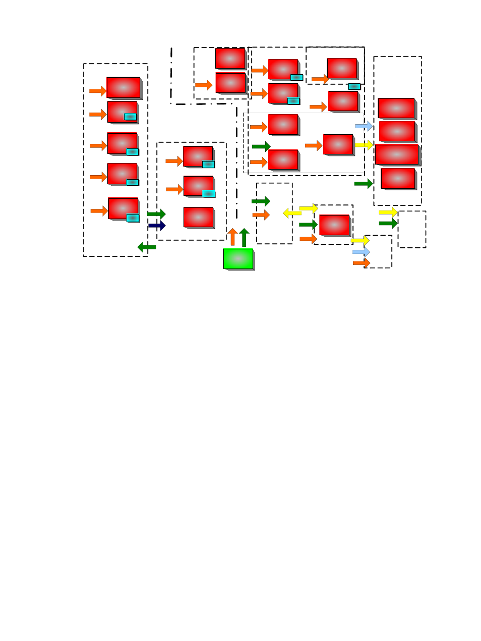
Figure 1-6 Power Subsystem Block Diagram
System POL Converters
Processor Side
I/O Side
BPS
(2)
Embedded design
V1P 5
POL
V1P 2
POL
Summit
Loop
V3P3
V3P 3
POL
V5P 0
POL
V12N
POL
Possibly share Source and Load
V5P 0
POL
Socha, Jim
Interconnect
CCA
V3P3
Summit
Loop 6
Processor BP
V1P 5
POL
V1P 2
POL
V1P 8
POL
Summit
Loop
Summit
Loop
CPU PODS
(2)
V12
V2P 5
POL
V2P 5
POL
PDH
I/O BP
Unified Core
V3P 3 is called
V3P 3_PCI
V2P 5_FPGA
embedded
V1P 8_RMP 3
embedded
V1P 8_SYS _PLL
embedded
V1P 2_FPGA
embedded
V1P 2
POL
V1P 8
POL
Summit
Loop
Mem Ext (2)
V0P 9
embedded
Tower of Power
V2P5
Summit
Loop
Summit
Loop
12/5/06
12/24 DIMM
12/24 DIMM
12/24 DIMM
Fan contlr
POL
Fan contlr
POL
V5P0
Mid-Plane
V3P3
CIOBP – Target CCA
Summit
Loop
Summit
Loop
Summit
Loop
FPD CCA
SAS CCA
V3P3
V5P0
V3P3
V
3P
3
_
S
T
B
Y
V3P 3_STBY
V3P 3_STBY
V3P 3_STBY
V3P 3_STBY
V3P 3_STBY
V3P 3_STBY
V3P 3_STBY
V12
V12
V12
V12
V12
V12
V12
V12
V12
V12
V12
V12
V12
V12
V12
V12
V
1
2
V1P 0
POL
V12
Two hot-swappable ac/dc power supplies generate main system power, and a standby power
voltage. One active power supply is sufficient to operate the system at maximum load. Each
power supply receives ac power through the integrated ac inlet. The system can operate at 100-240
VAC and achieve 1+1 redundancy. The power supplies are power factor corrected and the
maximum dc power output of the power system is 1095 watts. Service the hot-swappable power
supplies are serviced by sliding them out the rear of the chassis.
Applying system power in normal customer usage, the rx3600 runs on 100 to 240 V. Standby
power will be supplied on either; hence the BMC will power up when the power supplies are
plugged in. The BPS0_AC_OK and BPS1_AC_OK signals indicate whether the ac voltage to the
power supplies is within the required range. If neither BPS0_AC_OK nor BPS1_AC_OK is asserted,
then the BMC should log an event and prevent the system from turning on.
Power Button
The power button on the rx3600 is a momentary contact push button. The BMC
polls the front panel power button at a rate of at least 2 Hz. The power button is an input to the
System Power State Management. If the system is off, a single button press will turn on the
system. If the system has booted to an OS, and a short button press is detected, a
graceful-shutdown request will be sent to the system by pulsing ACPI_PWR_BTN_L; when the
ACPI bits are set to note the O/S has shut down, the BMC will perform a hard power down. If
the system has not booted to an OS, or if a long (5 second) button press is detected, the system
will do an immediate hard power off.
System Power State Management
The system power may be controlled from the power button,
an IPMI Chassis command, Wake-On-LAN, loss or gain of ac.
Power On Sequence:
1.
Update the cache of DIMM SPD information.
2.
Ensure that the memory board is detected and that the cpu board has a processor in socket
0. If these FRUs are not detected the BMC logs an event against the Missing Device sensor
(sensor 0x15).
3.
Check for a BPS0_AC_OK or a BPS1_AC_OK signal. If neither is asserted, then the ac supply
has a problem.
4.
If any FRUs are missing or both ac supplies are not valid, then return to power off state.
Server Subsystems
33