Setting data clock direction (dte or dce) – Emulex DCP_link User Manual
Page 23
Hardware Configuration 2-9
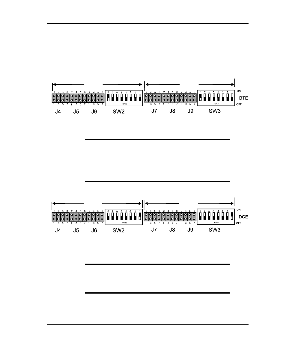
Setting Data Clock Direction (DTE or DCE)
J7, J8, J9 and SW-3 set the synchronous data clock direction (DTE or DCE)
for port 1. Jumpers J4, J5, J6 and SW2 set the synchronous data clock
direction (DTE or DCE) for Port 2.
Figure 2-7 Factory Default DTE Settings All Modes Except V.35
NOTE: DTE OPERATION RS422: In the RS422 mode
additional flexibility is provided to terminate
receivers with 100 ohm resistors. If termination
resistors are required in this mode, additional
switches SW3 - 2, 3 and 4 should be CLOSED (SW2
for Port 2).
PORT
2
PORT
1
PORT
2
PORT
1
Figure 2-8 DCE Settings All Modes Except V.35
NOTE: DCE OPERATION RS422 Port 1: In RS422 DCE
mode, if termination resistors are required,
additional switch SW3 - 2 should be CLOSED
(SW2 for Port 2).