Yaskawa i80M Maintenance Manual User Manual
Page 117
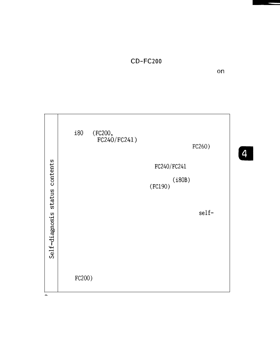
( 6 ) L E D D i s p l a y
Self-diagnosis results are displayed on 7-segment
LED on the model JAN
board.
( a ) I n i t i a l S e l f - D i a g n o s i s S t a t u s D i s p l a y a t P o w e r
Pass indication is made on the initial self-diagnosis
display screen at power on. At the same time,
t h e
same number as in the pass indication is displayed
on the 7-segment LED.
O: Local RAM check path (FC200)
1: Bus gate set path
:
FC21O, FC222/FC224, FC230B,
i80B : (FC200, FC21O, FC250/FC251,
2: A-common RAM check path
3: CPU activation check path among FC200, FC21O,
FC222/FC224, FC230B and
( i80)
CPU activation check path among FC200, FC21O,
FC250/FC251, FC260 and FC265
4: Option RAM check path
& system
configuration parameter information transfer
path
5: First request path from model JANCD-FC200
6: Operation processor initialization &
diagnosis
7: Path for supplying a clock to each CPU
8: Parameter common, local RAM transfer path
9: Common and local RAM transfer paths of offset
and macro information
A: CMOS fixed file check path (screen 10)
B: Inter-CPU regular operation check started
(screen 11)
C: CPU normal mode setup completed (except for
(screen 12).
D: CPU normal mode (except for FC200) (screen 13)
(b) System Operation Display
The point of the 7-segment LED blinks about every
one second.
The system is operating normally while
it is blinking.
109