9 adapter kit for non-heidenhain wiring – HEIDENHAIN PWM 8 User Manual
Page 79
- 79 -
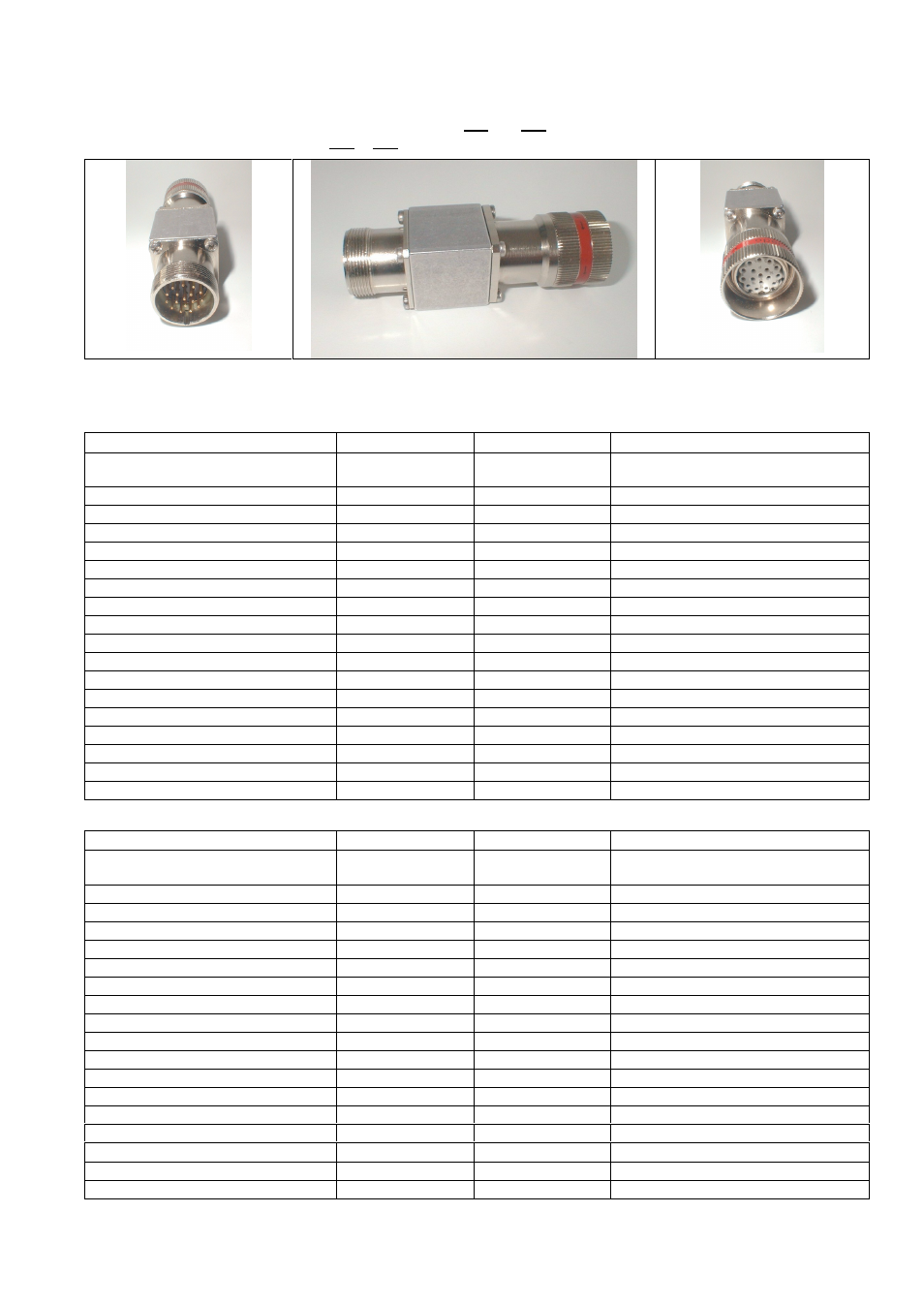
18.9 Adapter kit for non-HEIDENHAIN wiring
To adapt PWM8 interface boards with Pos.Enc. wiring (position encoder) to motor encoder wirings
Mot.Enc.1Vpp and Mot.Enc.EnDat (motor encoder 1Vpp / EnDat)
18.9.1 Adapter kit 1 (Zn/Z1) for operation with Siemens and JH drives with
HEIDENHAIN Zn/Z1 encoders and non-HEIDENHAIN wiring
Kit 1: Adapter Zn/Z1 IN: Id.No. 349312-01 for flange socket IN of interface board
PWM8 side (Pos.Enc.1Vpp)
Signal
Color
Drive side (Mot.Enc.1Vpp)
Flange socket 17-pin, male
Flange socket 17-pin,
knurled coupling ring
PIN 1
Up sensor
Blue
PIN 16
PIN 2
R-
Black
PIN 13
PIN 3
R+
Red
PIN 3
PIN 4
0V sensor
White
PIN 15
PIN 5
Temp.+
Green
PIN 8
PIN 6
Temp.-
Brown
PIN 9
PIN 7
Up
Brown/green
PIN 10
PIN 8
D-
Violet
PIN 4
PIN 9
D+
Yellow
PIN 14
PIN 10
0V
White/green
PIN 7
PIN 11
Internal shield
-
PIN 17
PIN 12
B+
Blue/black
PIN 11
PIN 13
B-
Red/black
PIN 12
PIN 14
C+
Gray
PIN 5
PIN 15
A+
Green/black
PIN 1
PIN 16
A-
Yellow/black
PIN 2
PIN 17
C-
Pink
PIN 6
Kit 1: Adapter Zn/Z1 OUT: Id.No. 349312-02 for flange socket OUT of interface board
Drive side (Mot.Enc.1Vpp)
Signal
Color
PWM8 side (Pos.Enc.1Vpp)
Flange socket 17-pin, male
Flange socket 17-pin,
knurled coupling ring
PIN 16
Up sensor
Blue
PIN 1
PIN 13
R-
Black
PIN 2
PIN 3
R+
Red
PIN 3
PIN 15
0V sensor
White
PIN 4
PIN 8
Temp.+
Green
PIN 5
PIN 9
Temp.-
Brown
PIN 6
PIN 10
Up
Brown/green
PIN 7
PIN 4
D-
Violet
PIN 8
PIN 14
D+
Yellow
PIN 9
PIN 7
0V
White/green
PIN 10
PIN 17
Internal shield
-
PIN 11
PIN 11
B+
Blue/black
PIN 12
PIN 12
B-
Red/black
PIN 13
PIN 5
C+
Gray
PIN 14
PIN 1
A+
Green/black
PIN 15
PIN 2
A-
Yellow/black
PIN 16
PIN 6
C-
Pink
PIN 17