HEIDENHAIN PWM 8 User Manual
Page 12
- 12 -
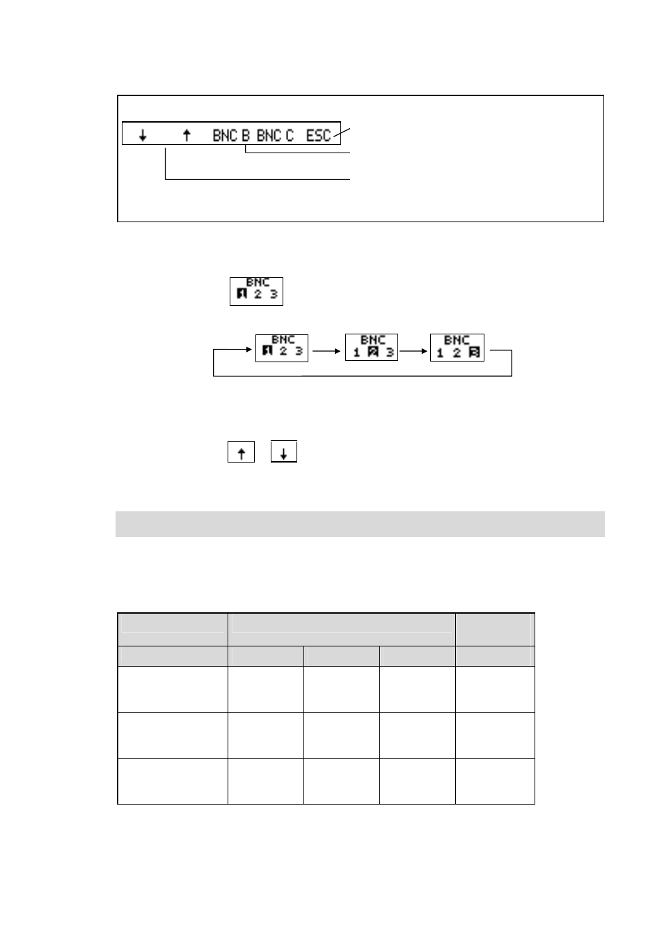
If e.g. the soft key BNC A is pressed, the assignment of the BNC socket A can be changed:
Terminate BNC assignment
Assignment of sockets B and C can be selected
Arrow keys to change the encoder signals of the
selected BNC socket A
Switching the BNC memory:
The assignment of the BNC sockets is stored in three BNC memories that can be called
successively.
Each time the soft key
is pressed, the next BNC memory is activated.
The display of the active BNC memory is highlighted:
Changing the signals in the BNC memories 1 to 3:
The signal in the active BNC memory is automatically stored each time it is changed by
pressing the soft keys
or
.
After power interruption the signals of the BNC memory active last are allocated to the BNC
sockets.
Notes on the use of the BNC sockets:
•
When using the BNC sockets to measure the encoder signals with an oscilloscope,
be sure that the workstation and the operator are properly grounded!
•
A floating oscilloscope should be used to display the encoder signals with as little interference
as possible. Always connect the oscilloscope to the socket of the switch cabinet of the machine
tool to avoid signal distortions caused by different ground potentials.
The following encoder signals can be connected with the BNC sockets:
Interface Board
Encoder signals on BNC socket
BNC
memory
BNC A
BNC B
BNC C
11µApp
Ue1
U1+2
Ue0
Ue2
U1+2
Ue0
Ue0
NTR
/UaS *)
1
2
3
1Vpp
A
A+B
R
B
A+B
R
R
NTR
/UaS *)
1
2
3
TTL, HTL
Ua1
/Ua1
Ua0
Ua2
/Ua2
/Ua0
Ua0
/Ua0
/UaS
1
2
3
*) Signal is generated in the PWM 8.