4 output signals htl – HEIDENHAIN PWM 8 User Manual
Page 55
- 55 -
12.1.4 Output Signals
HTL
HTL square-wave signals
The design of encoders with HTL square-wave signals is similar that of encoders with TTL square-wave
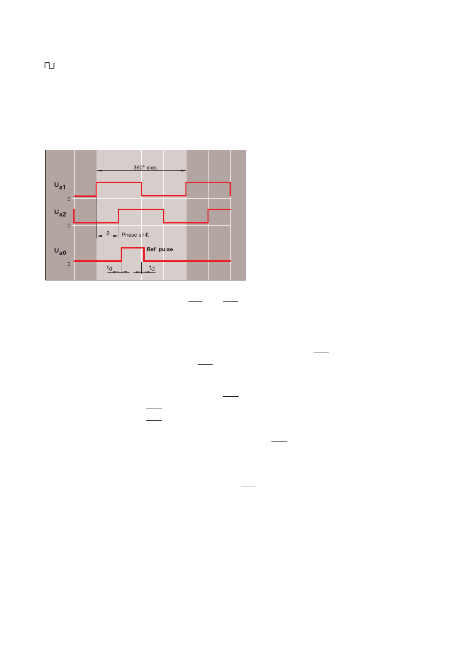
signals. Output signals are HTL square-wave pulse trains Ua1 and Ua2 together with the reference pulse
Ua0 that is gated with the incremental signals Ua1 and Ua2.
To each square-wave pulse train the integral electronics in addition outputs the corresponding inverted
signal (not with ERN 1030). The outputs of encoder with HTL square-wave signals are short-circuit proof at
room temperature.
Incremental signals:
HTL square-wave pulse trains Ua1 and Ua2 and their inverted
pulse
trains
Ua1
and
Ua2
(ERN 1030: no inverted pulse trains).
Ua2 lags Ua1 with ccw rotation (view on shaft or encoder flange).
Edge separation
a
≥
0.45 µs at 300 kHz scanning frequency
a
≥
0.8 µs at 160 kHz scanning frequency
The scanning frequency depends on the encoder model and can be seen from the specifications.
Ref. mark signal
1 square-wave pulse Ua0 and its inverted pulse
Ua0
ERN
1030:
no
Ua0
Pulse width
90° elec.
Delay time
Itdl
≤
50 ns for gated ref. pulse
Fault detection signal
1 square-wave pulse
UaS
UaS
= LOW: fault detected
UaS
= HIGH: encoder operates properly
(short circuit not permissible after Up)
ERN 1030: no fault detection signal
UaS
Signal level HTL
UH
≥
21 V with
−
IH = 20 mA
UL
≤
2.8 V with IL = 20 mA
if supply voltage is +24 V, without cable
Load capacity
−
IH
≤
200 mA (not true for
UaS
)
IL
≤
200 mA
CLoad
≤
1000 pF
Switching times
Rise time:
t+
≤
200 ns
Fall
time:
t
−
≤
200 ns