HEIDENHAIN PWM 8 User Manual
Page 78
- 78 -
Serial SSI output signals
With transfer of the absolute position information, the absolute position value is transferred synchronously to
a CLOCK given by the control, starting with the most significant bit (MSB first).
According to the SSI standard the data word length is 13 bits for single-turn encoders and 25 bit for multi-turn
encoders.
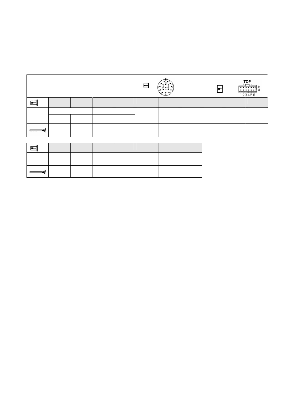
18.8.3 1 Vpp measuring system with programmed SSI interface
17-pin HEIDENHAIN flange socket
Interface board flange socket:
IN
Interface board flange socket:
OUT
15
16
12
13
14
17
8
9
7
10
A B
+
– + –
+DATA
-DATA
+CLOCK
-CLOCK
10V-30V
UP
0 V
UN
Green /
Black
Yellow /
Black
Blue /
Black
Red /
Black
Gray
Pink
Violet
Yellow
Brown /
Green
White /
Green
11
1
4
3
2
5
6
Internal
shield
RxD
TxD
/Uas
1)
Dir. of
rotation
Preset1
Preset2
-
Blue
White
Red
Black
Green
Brown
1): PWM8 displays the encoder error signal as /UaS2 (see also section: 1 Vpp encoders with programmed
SSI interface)
Programmable SSI 09/10 encoders
HEIDENHAIN offers programmable versions of the multi-turn encoders ROQ 425, EQN 425 and single-turn
encoders ROC 413, ECN 413. The following parameters and functions must be programmed via software:
•
Single-turn resolution up to 8192 absolute positions per revolution. This allows for e.g. the adaptation
to any screw pitch.
•
Multi-turn resolution up to 4096 distinguishable revolutions, e.g. for the adaptation to any screw pitch.
•
Direction of rotation for ascending position values.
•
Output format of the position value: Gray code or dual code.
•
Data format: synchronous-serial right-aligned or 25-bit partitioned data format (SSI).
•
Offset and preset values for zero rest or compensation.
Some of these functions can also be activated by means of connecting elements:
•
Direction of rotation for ascending position values.
•
Setting the preset value defined by software programming.
Moreover, the HEIDENHAIN programmable multi-turn encoders feature a diagnosis function providing
information on the current operating status. The PLC can evaluate an interference signal output on a separate
line. Thus, the standstill time of the system can be reduced.
Details: see Operating Instructions
Software for programmable SSI encoders Id.No. 332434-10
PCB connector
on encoder
: