Pin layouts of standard heidenhain cables 11µapp – HEIDENHAIN PWM 8 User Manual
Page 60
-
60
-
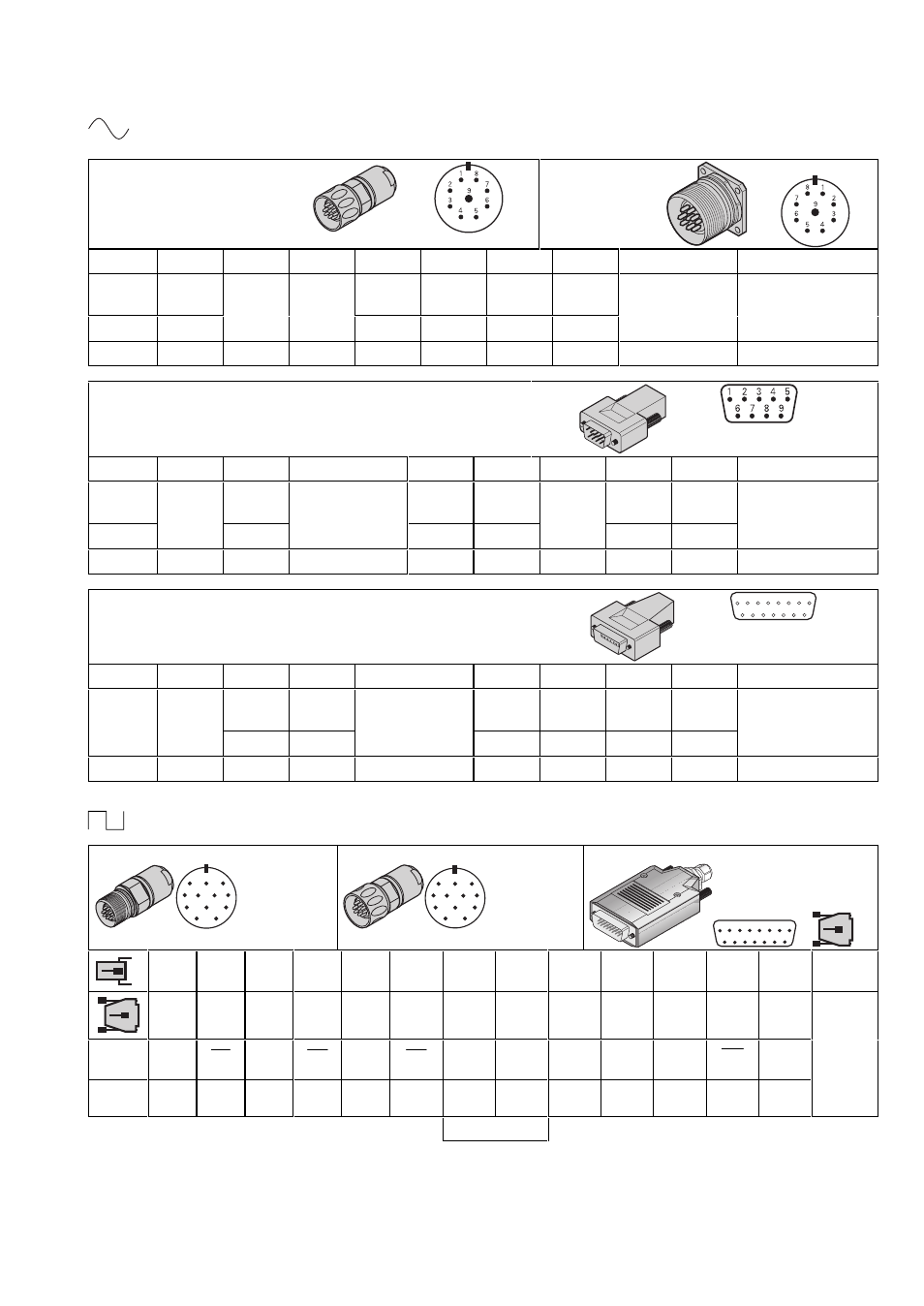
14. Pin Layouts of Standard HEIDENHAIN Cables
11µApp
9-pin
HEIDENHAIN connector
9-pin
flange socket
1 2 3 4 5 6 7 8
9
housing
I1
I1 5V
Up
0V
UN
I2
I2
I0
I0 internal
shield external
shield
+
−
+
−
+
−
Green Yellow Brown White Blue Red Gray Pink
White/brown
9-pin D-sub-connector
for HEIDENHAIN IK 121A counter card
1 2 3
4
5 6 7 8 9
housing
I1 0V
UN
I2 internal
shield
I0
I1 5V
Up
I2
I0 external
shield
−
−
−
+ + +
Yellow White Red
White/brown
Pink Green Brown Blue Gray
15-pin D-sub-connector
for HEIDENHAIN contouring control TNC 410, TNC 426, TNC 430
1
9
2
10
3
5
4
6
8
7
11 12 13 14 15
1 2 3 4
5
6 7 10
12
housing
5V
Up
0V
UN
I1
I1 internal
shield
I2
I2
I0
I0 external
shield
+
−
+
−
+
−
Brown White Green Yellow White/brown
Blue Red Gray Pink
TTL
12-pin HEIDENHAIN-coupling
1
7
6
5
4
3
2
9
12
11
8
10
12-pin HEIDENHAIN-connector
1
2
3
4
5
6
7
9
10
11
8
12
15pin D-sub-connector (male) at LIF 171
1
9
2
10
3
5
4
6
8
7
11 12 13 14 15
5 6 8 1 3 4 12 10 2 11 9 7 /
housing
1 9 3 11
14 7 4 2 12 10 / 13 15
external
shield
Ua1
Ua1
Ua2
Ua2
Ua0
Ua0
5V
Up
0V
UN
5V
sensor
0V
sensor
frei
UaS
1)
Brown
Green
Gray
Pink
Red
Black
Brown/
green
White/
green
Blue White / Violet Yellow
IEC742
EN
50178
Sensor line internally connected to power supply line. Shield on housing.
1) Switchover TTL/11µApp