HEIDENHAIN PWM 8 User Manual
Page 51
- 51 -
12.1 Description of the Output Signal
12.1.1 Output Signals
11 µApp
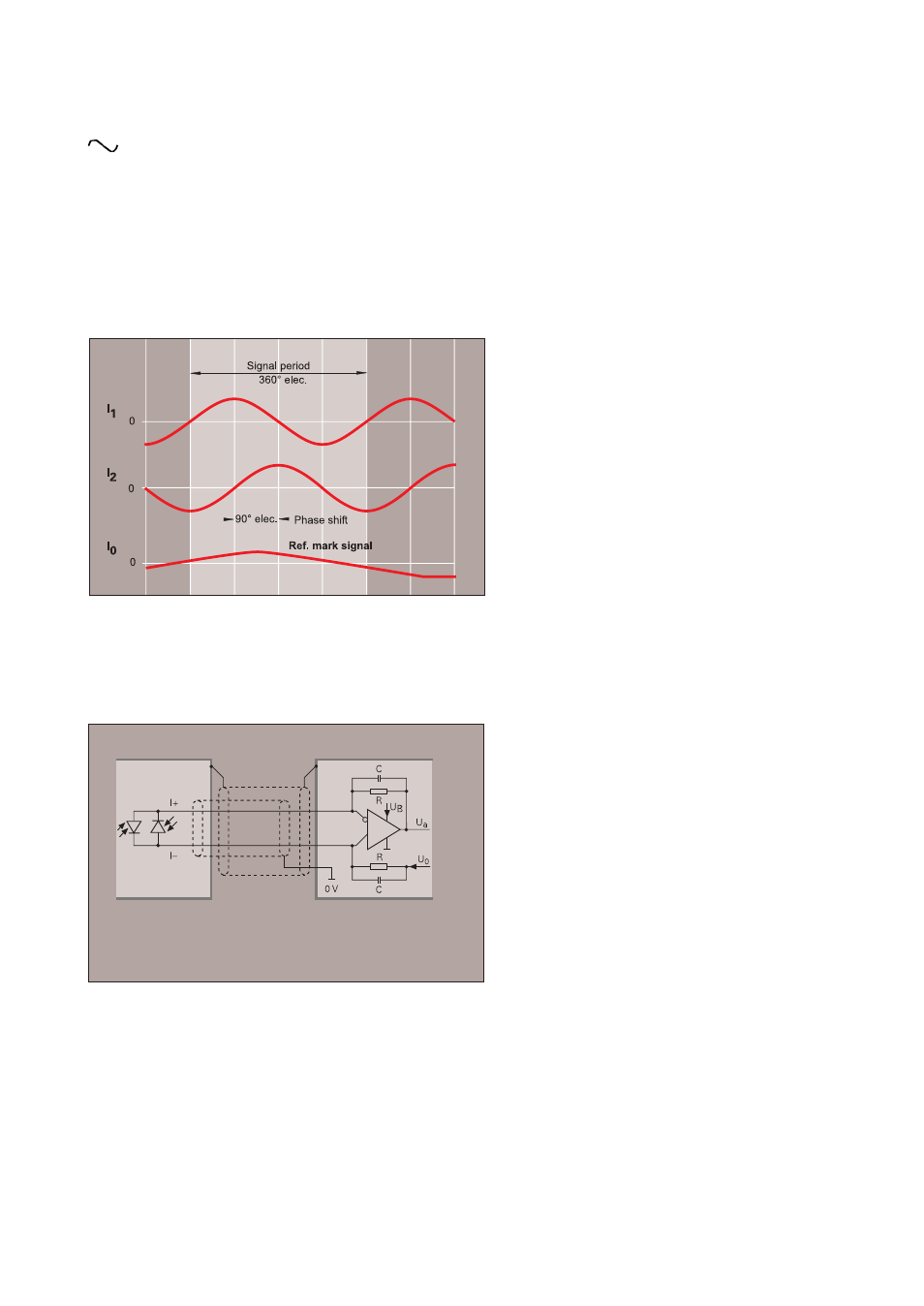
Current signals
The sinusoidal incremental signals I1 and I2 are phase-shifted by 90°; their level is approx.
11 µApp. The peaks of the ref. mark signals I0 have a usable component of ca. 5.5 µA.
The current signal of the incremental linear encoders can be interpolated and digitized either in the
subsequent electronics, e.g. HEIDENHAIN ND position display or TNC numeric control or in a separate
HEIDENHAIN EXE interpolation and digitizing electronics. For current signals the maximum cable length
between linear encoder and subsequent electronics is 30 m provided that original HEIDENHAIN cables are
used.
* These values apply for Up = 5 V
±
5% at the source, cable lengths up to 30 m and a
cross-section of the power supply line of 1 mm². The signal amplitude changes with
increasing scanning frequency.
Recommended input circuit of the subsequent electronics
Incremental signals
2 sinusoidal signals I1 and I2
signal amplitude*
I1, I2: 7 to 16 µApp
Reference mark signals
1 or several peaks I0
signal amplitude with 1 k
Ω
load
I0 ca. 5.5 µA (usable component)
Example:
Cable length
Max. 30 m (distributed capacitance 90 pF/m)
when using original HEIDENHAIN cables
-3dB cutoff frequency of input circuit
approx. 60 kHz
Dimensioning
Differential line receiver RC4157
C = 27 pF
R = 100 k
Ω
±
2%
U0 = UB/2
UB = +15 V