A+b), Interface 1 vss, Bnc bnc a ue0 – HEIDENHAIN PWM 8 User Manual
Page 50: Bnc b 1+2
- 50 -
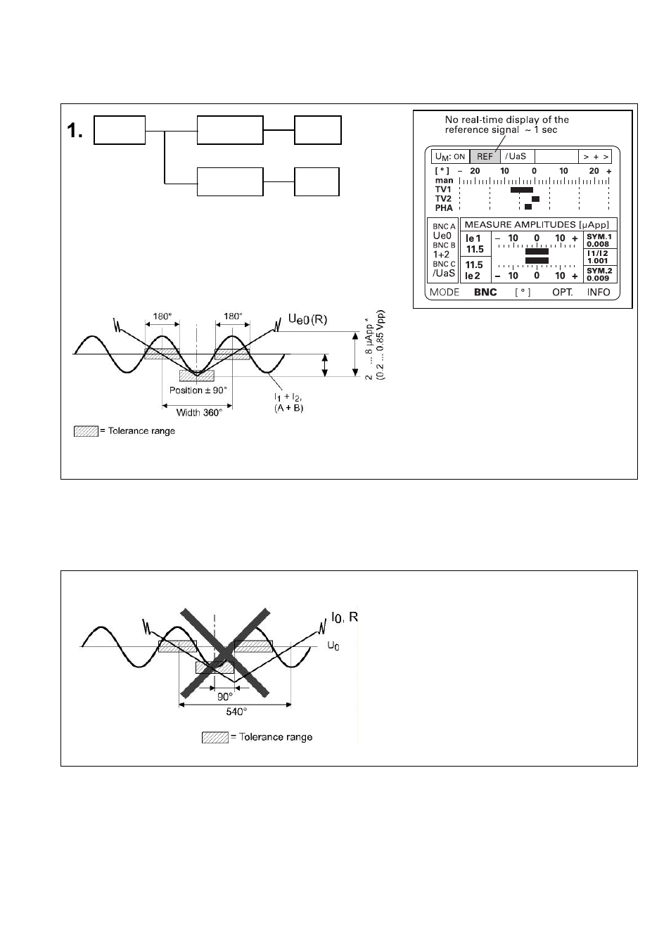
PWM 8 Settings reference mark
* Interface 1 Vss
*
Old LS series:
LS 50x; LS 80x
(e.g. LS 503; LS 803)
I
0
= 5 ... 15µAss
Schematic display of I1+I2 (A+B) on the
oscilloscope.
Example:
Reference mark signal
Caution: The reference-mark edges (ref. Mark / Uo line) must not intersect outside
the tolerance range!
Note:
The quality of the output signals has an influence on the measuring accuracy of the linear and rotary
encoders.
The tolerances stated are valid for standard applications of HEIDENHAIN encoders (e.g. LS on machine tools
with measuring steps up to 1 µm).
For operation with encoders with higher accuracy (e.g. exposed, contactless encoders, angle encoders and
encoders with highly interpolated output signals) the tolerances for the output signals are smaller.
HEIDENHAIN compares precision encoders to a measuring standard after adjustment.
BNC
BNC A
Ue0
(A)*
BNC B
1+2
(A+B)*