2 output signals 1vpp – HEIDENHAIN PWM 8 User Manual
Page 52
- 52 -
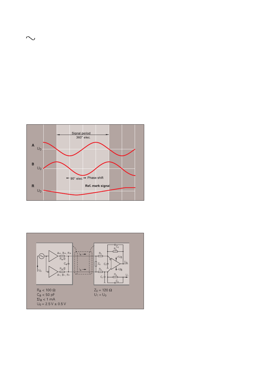
12.1.2 Output Signals
1Vpp
Voltage signals
The sinusoidal incremental signals A and B are phase-shifted by 90°; their level is approx. 1 Vpp. The peaks
of the ref. mark signals have a usable component of ca. 0.5 V.
Encoders with a Z1 track additionally output the signals C and D. The specification of these signals is
identical to that of the incremental signals (see section 13, adapter connector).
When using original HEIDENHAIN cables, voltage signals can be transferred over a distance of 150 m to the
subsequent electronics. For this purpose a supply voltage of 5 V
±
5% or 5 V
±
10% (depending on the
encoder model) must be ensured at the encoder. Encoders that output voltage signals feature connectors for
the sensor lines which serve to measure the supply voltage at the unit. By means of appropriate controlling
means in the subsequent electronics the tolerance of the supply voltage can be observed.
Sinusoidal voltage signals can be highly interpolated.
Output signals measured with PWM 8
* These values apply for Up = 5 V
±
5% or Up = 5 V
±
10% at the encoder.
The signal amplitude changes with increasing scanning frequency.
Recommended input circuit of the subsequent electronics
Incremental signals
2 sinusoidal signals A and B
signal amplitude* approx. 1Vpp
A, B: 0.6 to 1.2 Vpp
with terminating resistor Z0 = 120
Ω
Reference mark signal
1 or several peaks R
signal amplitude approx. 0.5 V
R: 0.2 to 0.8 V (usable component)
with terminating resistor Z0 = 120
Ω
Example:
Cable length
Max. 150 m (distributed capacitance 90 pF/m)
when using original HEIDENHAIN cables
-3dB cutoff frequency of input circuit
approx. 100 kHz
Dimensioning
Differential line receiver RC4157
R1 = 10 k
Ω
and C1 = 220 pF
R2 = 34,8 k
Ω
and C2 = 10 pF
UB =
±
15V