HEIDENHAIN PWM 8 User Manual
Page 30
-
30
-
Basic circuit diagram of the power supply of the encoder with the power supply unit connected:
p§F¤zzd©¤ma
§a4^amVFV¤d"p§a^p¤
zpFma"dFVFV"apm
G
mFm"dG
zp§F¤zzd©
4pm¦FF
p
F
m4
p=
F
¤z
zd
©
The standard setting of the encoder power supply is 5V; when operating with HTL interface board without
subsequent electronics 12V.
Current consumption of PWM 8 when powered via DC-IN socket:
(measured with 11µApp interface board)
Voltage at DC-IN
10 V
12 V
15 V
20 V
24 V
30 V
PWM 8 current consumption
500 mA
420 mA
350 mA
270 mA
230 mA
200 mA
PWM 8 current consumption
with encoder (100 mA)
580 mA
480 mA
400 mA
310 mA
260 mA
220 mA
6.1.2 Power Supply of PWM 8 and Encoder via the Encoder Output
(OUT) of the Interface Board
PWM 8 can be integrated into the encoder circuit. For this purpose the subsequent elec-tronics must be
connected to the encoder output (OUT) of the interface board. The supply voltage for PWM 8 is taken from
the subsequent electronics. In order to reduce the power consumption of the subsequent electronics, the
background lighting of the display is auto-matically switched off!
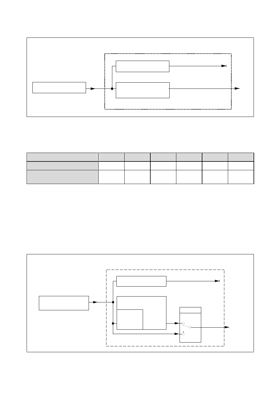
Basic circuit diagram of the power supply of encoder and PWM 8 with subsequent electronics
connected (with interface board 11µApp, 1Vpp, TTL):
¤*F¤FmFdF4pma4
ssk zz:szz:
§a4^amVFV¤d"p
G
mFm"dG
zp§F¤zzd©
4pm¦FF
p
F
m4
p=
F
¤z
zd
©
pFma"d
FVFV"apm
""h¢
Odp"amV
Oph
4¤phF