HEIDENHAIN PWM 8 User Manual
Page 22
- 22 -
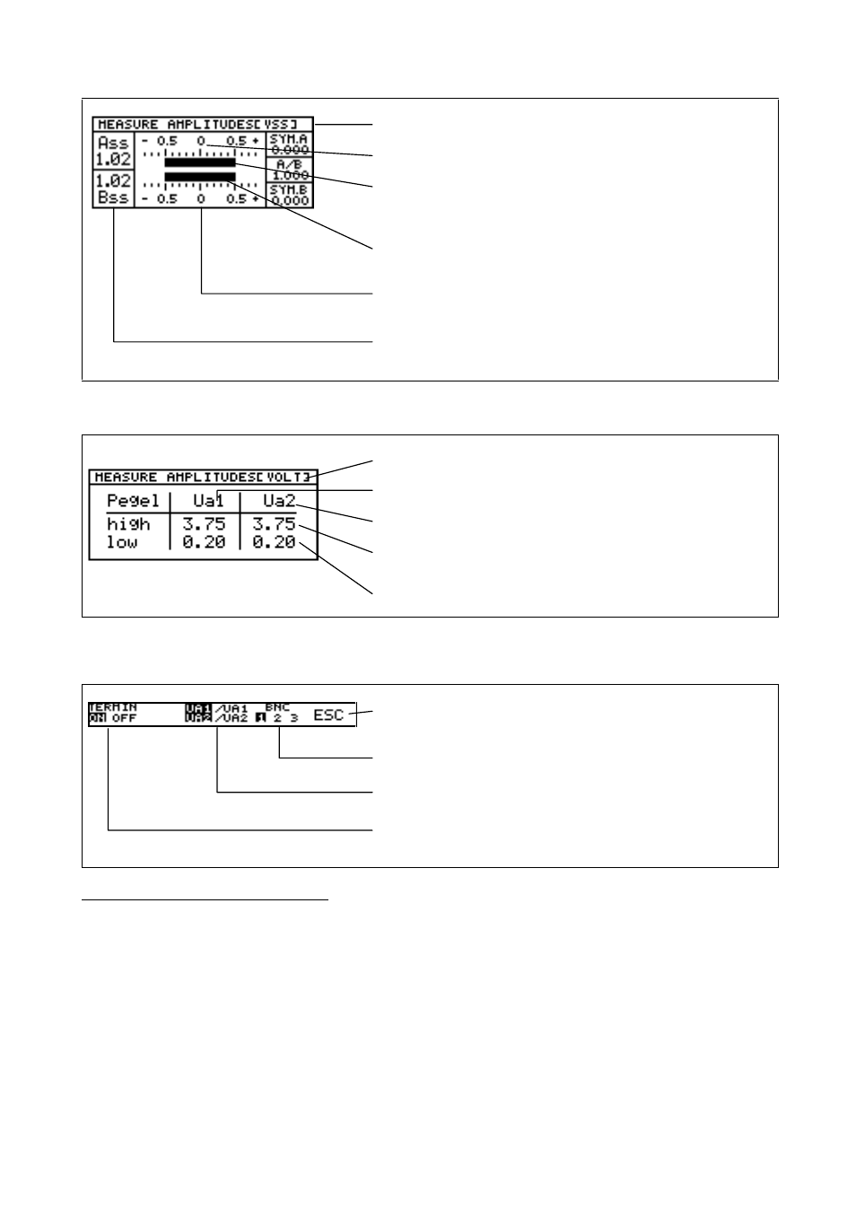
Result is displayed in Vpp.
Datum for measurement of sign. amplitude (U
0
)
Bar display of incremental signal A.
The position of the bars stands for the symmetry
of the incremental signals.
Bar display of incremental signal B.
Range for measurement of the signal amplitude;
here: 1.66 Vpp
Numerical peak-to-peak value of the signal amplitudes of the
incremental signals A and B in Vpp.
4.5.3 Measuring the Signal Amplitudes with TTL or HTL Interface Boards
Result is displayed in V
Incremental signal 1
Incremental signal 2
High level of a signal amplitude in V
Low level of a signal amplitude in V
The following options are available in the corresponding soft-key row:
Terminate measurement of signal amplitudes
Switch the BNC memory for BNC sockets A to C
Switch to inverted signals
Switch terminating resistors on and off (defined load of the
square-wave signals). The highlighted option is active.
Special feature of HTL interface board:
Up to software version 05:
With HTL encoders the inverted signals may not be available depending on the encoder.
Check whether the inverted signals are available before measuring the signal amplitudes. PWM 8 cannot
recognize, whether there are inverted signals or not!
If the inverted signals are missing, incorrect values are displayed for the signal amplitudes!
From software version 05:
If the encoder does not provide inverted signals, "------" is displayed for the signal levels of
the inverted signals.