HEIDENHAIN PWM 8 User Manual
Page 21
- 21 -
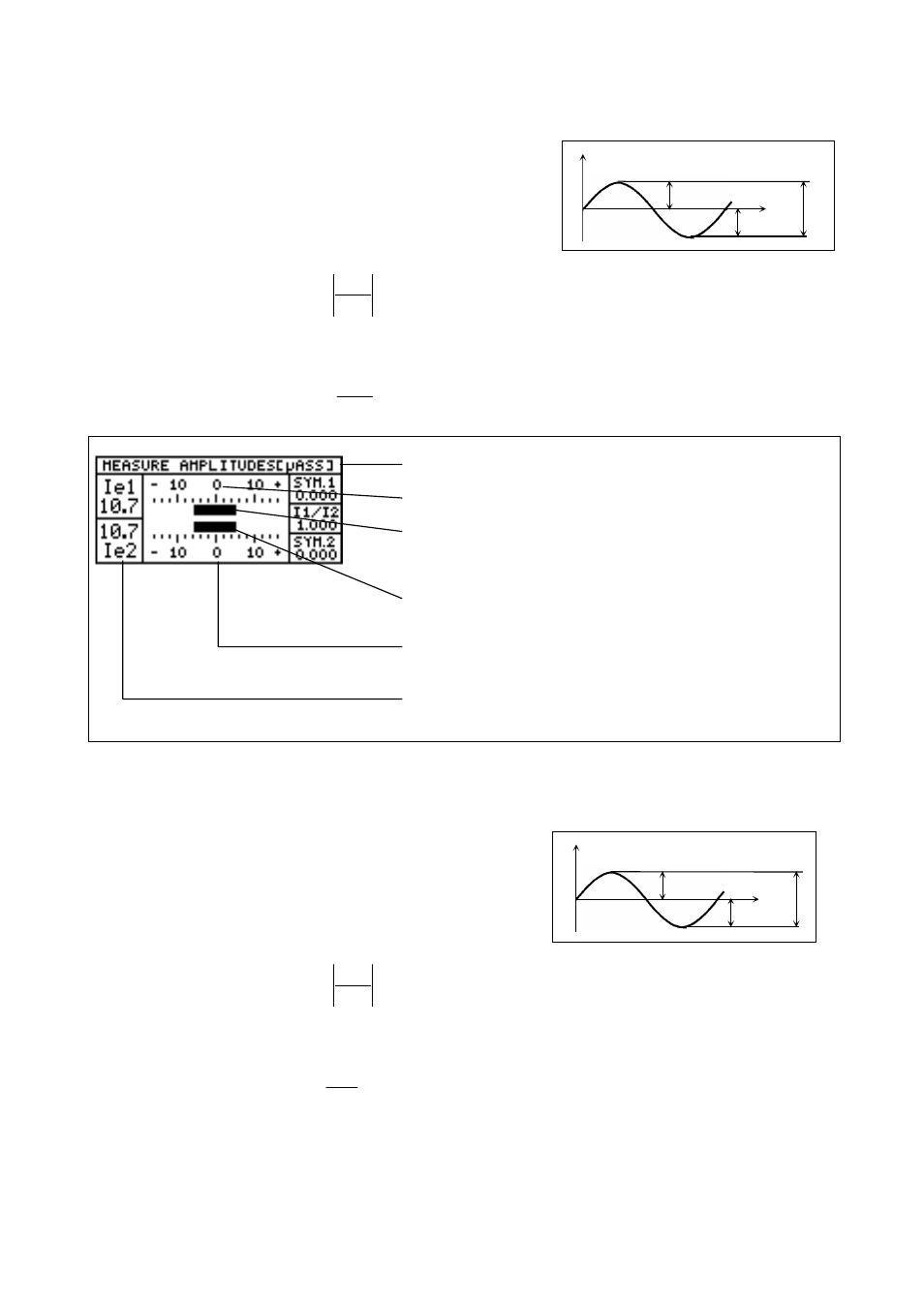
4.5.1 Measuring the Signal Amplitudes with 11µApp Interface Board:
Definitions:
SYM.1:
Symmetry 1, ratio of positive to negative
half wave of incremental signal Ie1 (versus U
0
)
SYM.2:
Symmetry 2, ratio of positive to negative
half wave of incremental signal Ie2 (versus U
0
)
Calculation:
a
b
2
c
-
´
Result: ideal = 0
I1 / I2:
Amplitude ratio, amplitudes of incremental signals Ie1 versus Ie2
Calculation:
C
C
Ie1
Ie2
Result: ideal = 1
Result is displayed in µApp
Datum for measurement of sign. amplitude (U
0
)
Bar display of incremental signal 1.
The position of the bars stands for the symmetry
of the incremental signals.
Bar display of incremental signal 2.
Range for measurement of the signal amplitude;
here: 33 µApp (
±
16.5µApp)
Numerical peak-to-peak value of the signal amplitudes of the
incremental signals 1 and 2 in µApp.
4.5.2 Measuring the Signal Amplitudes with 1Vpp Interface Board
Definitions:
SYM.A:
Symmetry A, ratio of positive to negative
half wave of incremental signal A, (versus U
0
).
SYM.B:
Symmetry B, ratio of positive to negative
half wave of incremental signal B, (versus U
0
).
Calculation:
a
b
2
c
-
´
Result: ideal = 0
A / B:
Amplitude ratio, amplitudes of incremental signals Ie1 versus Ie2
Calculation:
C
C
A
B
Result: ideal = 1
U
a
b
t
c
0
I
a
b
t
c
0