Interface board 1 vpp, Bnc bnc a ue1, Bnc b ue2 – HEIDENHAIN PWM 8 User Manual
Page 48: Mode measure amplitude [°] 25
- 48 -
Analog Output signals (~ 11 µApp/1 Vpp)
Prepare the oscilloscope as described below:
•
Vertical deflection
– Switch channels A and B to chop mode (CHOP).
– Set the deflection coefficient (Sensitivity) of the
channels A and B to 0.5 V/DIV (11µApp), 0.2 V/DIV
(1Vpp).
•
Horizontal deflection
– Set time coefficient (Time basis) to 0.5 ms/DIV.
•
Triggering
– Trigger automatically (AUTO)
– Trigger Channel A
– Trigger positive edge
•
Calibration
– Switch the input coupling switch (AC/DC/GND) of
the channels A and B to GND (
ç
or 0)
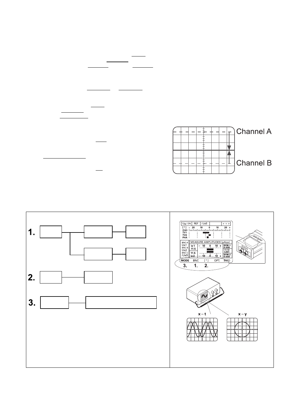
– Use the Y-position potentiometers of the channels
A and B to shift the electron rays congruently to the
center of the screen (fig.)
– Switch the input coupling switch (AC/DC/GND) of
the channels A and B to DC
.
PWM 8 Settings analog signals
* Interface board 1 Vpp
Possible oscilloscope display x - t or x - y
BNC
BNC A
Ue1
(A)*
BNC B
Ue2
(B)*
MODE
Measure amplitude
[°]
25°