Practical application – HEIDENHAIN PWM 8 User Manual
Page 29
-
29
-
6. Practical Application
6.1 Power Supply of PWM 8 and Encoder
6.1.1 Power Supply of PWM 8 and Encoder via DC-IN Socket
In general PWM 8 and the encoder can be powered from different sources. The table below contains an
overview of possible power supplies:
PWM 8 powered from
Power supply of encoder
24 V power
supply unit
subsequent
electronics
directly from
subs. electronics
floating
only 24V power supply unit
connected (DC-IN socket)
x
x
1)
only voltage from
subsequent electronics
connected (encoder output)
x
x
x
1)
24 V power supply unit and
voltage of subsequent
electronics connected
x
x
x
1)
1)
When using a HTL interface board, potential segregation is not possible.
As already mentioned in section 2 "General Information", PWM 8 may either be powered by the
24V power supply unit (standard set) or another dc voltage source of 10 - 30 V via the DC-IN socket. The
voltage at the DC-IN socket is referenced to the encoder voltage generated by PWM 8, i.e. if potential
segregation is required between PWM 8 and subsequent electronics, the voltage at the DC-IN socket must
be floating with relation to the subsequent electronics. The 24V power supply unit supplied with PWM 8
complies with this requirement.
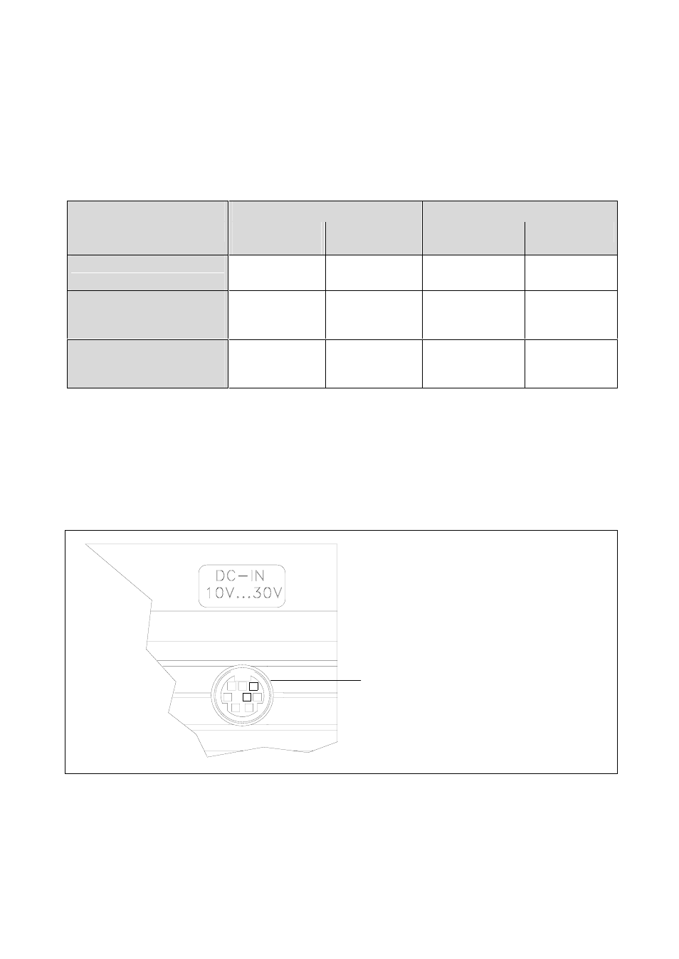
If the PWM 8 is operated via the DC-IN socket, it is always powered from this current source, irrespective of
whether an encoder voltage is fed at the encoder output of the interface board or not.
5
8 7 6
4 3
1
2
Socket for external power supply
(see section SPECIFICATIONS)
PWM 8 detail