3 output signals ttl – HEIDENHAIN PWM 8 User Manual
Page 53
- 53 -
12.1.3 Output Signals
TTL
TTL square-wave signals
Encoders that output TTL square-wave signals feature electronics that digitize the sinusoidal scanning
signals without interpolation.
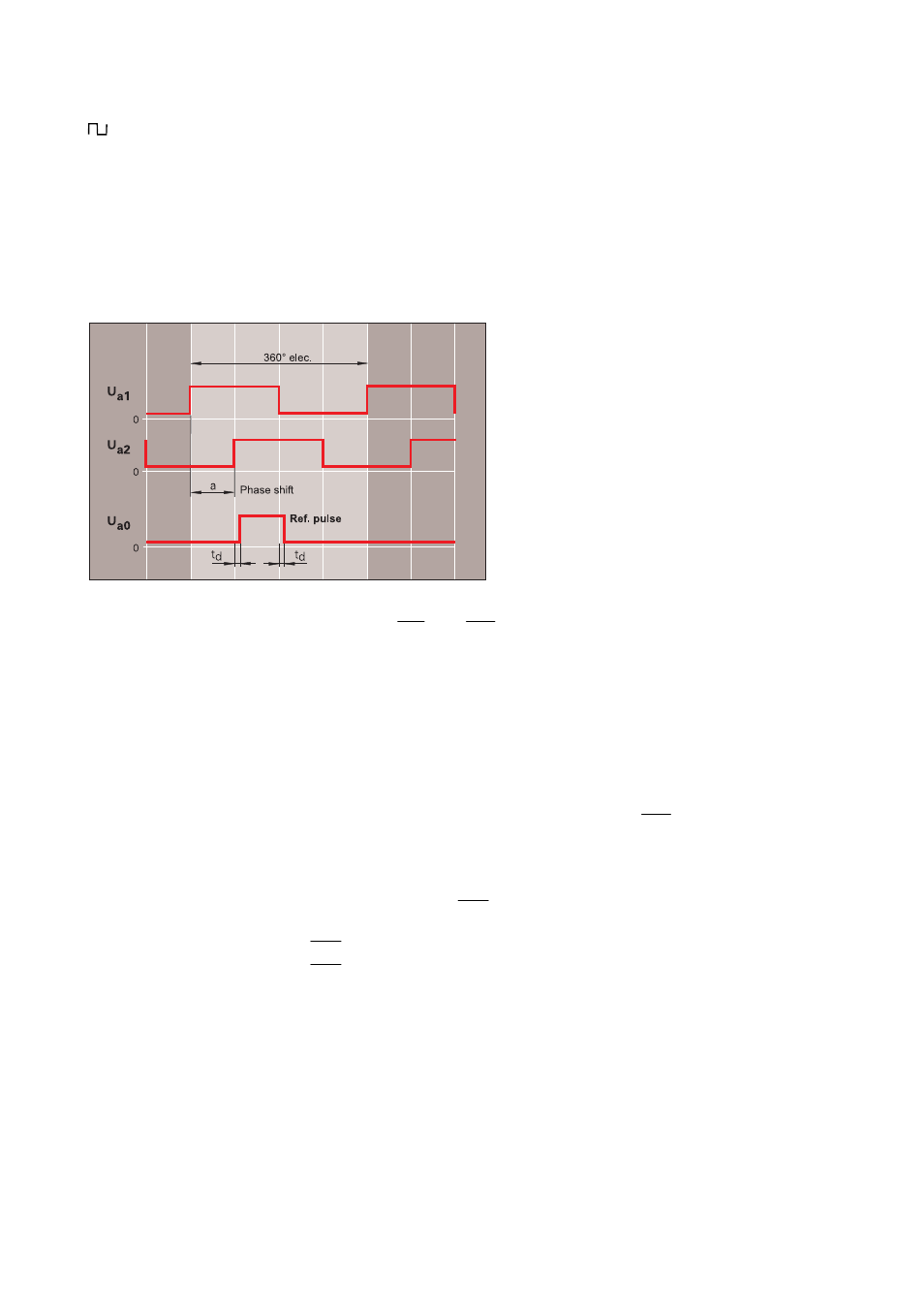
Two TTL square-wave signals Ua1 and Ua2 that are phase-shifted by 90° are output together with the
reference pulse Ua0 gated with the incremental signals Ua1 and Ua2. Encoders with distance-coded
reference marks output several Ua0 reference pulses.
The measuring step results from the distance between two edges of the signals Ua1 and Ua2.
To each square-wave signal the integral electronics in addition outputs the corresponding inverted signal.
Incremental signals
TTL square-wave signal trains Ua1, Ua2 and their inverted
signal
trains
Ua1
and
Ua2
.
Ua2 lags Ua1 with ccw rotation (view on shaft or on encoder
flange) or when the scanning unit moves away from the ID plate -
of the linear encoder.
Edge separation
a
≥
0.4 µs at 400 kHz scanning frequency
a
≥
0.45 µs at 300 kHz scanning frequency
a
≥
0.8 µs at 160 kHz scanning frequency
a
≥
1.3 µs at 100 kHz scanning frequency
The scanning frequency depends on the encoder model.
Reference mark signal
1 square-wave pulse Ua0 and its inverted pulse
Ua0
Pulse width
90° elec.
Delay time
Itdl
≤
50 ns
Fault detection signal
1 square-wave pulse
UaS
(single-ended signal: max. cable length 50m)
UaS
= LOW: fault detected
UaS
= HIGH: device operates properly