Pilot drilling (cycle 21), 21 pilot drilling (optional), 6 sl cy cles – HEIDENHAIN iTNC 530 (340 49x-01) User Manual
Page 376
376
8 Programming: Cycles
8.6 SL Cy
cles
PILOT DRILLING (Cycle 21)
Process
1
The tool drills from the current position to the first plunging depth
at the programmed feed rate F.
2
When it reaches the first plunging depth, the tool retracts in rapid
traverse FMAX to the starting position and advances again to the
first plunging depth minus the advanced stop distance t.
3
The advanced stop distance is automatically calculated by the
control:
At a total hole depth of up to 30 mm: t = 0.6 mm
At a total hole depth exceeding 30 mm: t = hole depth / 50
Maximum advanced stop distance: 7 mm
4
The tool then advances with another infeed at the programmed
feed rate F.
5
The TNC repeats this process (1 to 4) until the programmed total
hole depth is reached.
6
After a dwell time at the hole bottom, the tool is returned to the
starting position in rapid traverse FMAX for chip breaking.
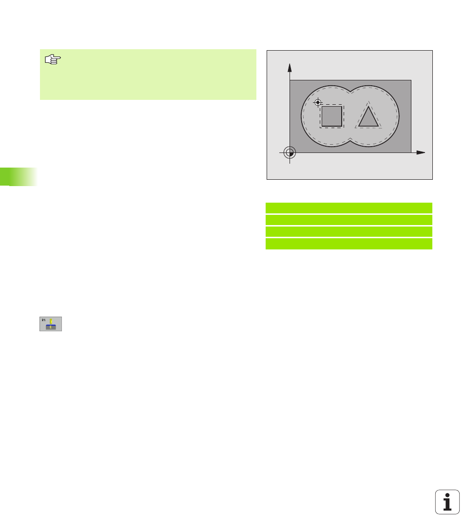
Application
Cycle 21 is for PILOT DRILLING of the cutter infeed points. It accounts
for the allowance for side and the allowance for floor as well as the
radius of the rough-out tool. The cutter infeed points also serve as
starting points for roughing.
8
Plunging depth
Q10 (incremental value): Dimension
by which the tool drills in each infeed (negative sign
for negative working direction).
8
Feed rate for plunging
Q11: Traversing speed in
mm/min during drilling.
8
Rough-out tool number
Q13: Tool number of the
roughing mill.
Example: NC blocks
58 CYCL DEF 21.0 PILOT DRILLING
Q10=+5
;INFEED DEPTH
Q11=100
;FEED RATE FOR PLUNGING
Q13=1
;ROUGH-OUT TOOL
X
Y
When calculating the infeed points, the TNC does not
account for the delta value DR programmed in a TOOL CALL
block.
In narrow areas, the TNC may not be able to carry out pilot
drilling with a tool that is larger than the rough-out tool.