Hardware installation, Prelude/concerto system diagram, Concerto installation notes – Grass Valley Prelude v.3.0 User Manual
Page 17: Prelude system cabling - concerto frame, Video/audio/reference, Network, Concerto frame, Figure 2. prelude/concerto system example
Prelude — Instruction Manual
17
Hardware Installation
Hardware Installation
Refer to the separate Acappella Instruction Manual or Concerto Installation and
Service Manual for detailed instructions on hardware installation.
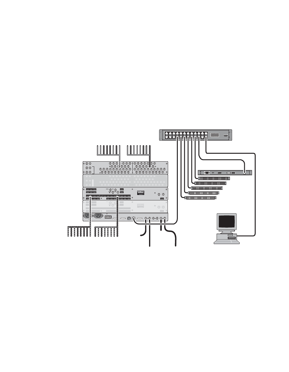
The following figures illustrate typical Prelude systems. Actual system
wiring will vary depending on the components making up your system.
Prelude/Concerto System Diagram
Figure 2. Prelude/Concerto System Example
25
21
17
13
9
5
1
22
18
14
10
6
2
26
23
19
15
11
7
3
28
27
30
29
31
32
24
20
16
12
8
4
31
27
23
19
15
11
7
28
24
20
16
12
8
32
29
25
21
17
13
9
30
26
22
18
14
10
5
6
3
4
1
2
INPUTS
OUTPUTS
EXP
IN
EXP
OUT
AUDIO/DATA
TDM
MON IN
MON OUT
1
2
1
2
EXT COM
2
EXT COM
1
E-NET
2
E-NET
1
AES REF
VID-REF 2
VID-REF 1
400W; 11.1A
36-60V
+
-
AC PWR 2
AC PWR 1
500W; 5A
50/60Hz
100-240V
ALARM
1 2 9 10
3 4 11 12
5 6 13 14
7 8 15 16
21 22 25 26
23 24 27 28
29 30 31 32 3 4 7 8
1 2 5 6
11 12 15 16
9 10 13 14
19 20 27 28
17 18 25 26
23 24
17 18
21 22
19 20
31 32
29 30
IN OUT
EXP. OUT
EXP. IN
1
1
2
2
OUTPUTS
INPUTS
IN
OUT
MONITOR
AES BALANCED BA
CKPLANE
+
G
+
G
1
1 2 9
2 9 10
10
3 4
3 4 11 12
11 12
5 6
5 6 13 14
13 14
7 8
7 8 15 16
15 16
21 22
21 22 25 26
25 26
23 24
23 24 27 28
27 28
29 30
29 30 31 32
31 32 3
3 4 7
4 7
8
1
1 2 5
2 5
6
11 12
11 12 15 16
15 16
9 10
9 10 13 14
13 14
19 20
19 20 27 28
27 28
17 18
17 18 25 26
25 26
23 24
23 24
17 18
17 18
21 22
21 22
19 20
19 20
31 32
31 32
29 30
29 30
IN OUT
IN OUT
EXP
EXP. OUT
. OUT
EX
EXP.
P. IN
IN
1
1
2
2
OUTPUT
OUTPUTS
INPUT
INPUTS
IN
IN
OUT
OUT
MONITO
MONITOR
AES BALANCED BA
AES BALANCED BA
CKPLANE
CKPLANE
+
G
+
G
+
G
+
G
25
25
25
21
21
21
17
17
17
13
13
13
9
5
9
5
9
5
1
1
22
22
22
18
18
18
14
14
14
10
10
10
6
2
6
2
6
2
26
26
26
23
23
23
19
19
19
15
15
15
11
11
11
7
3
7
3
7
3
28
28
28
27
27
27
30
30
30
29
29
29
31
31
31
32
32
32
24
24
24
20
20
20
16
16
16
12
12
12
8
4
8
4
8
4
31
31
31
27
27
27
23
23
23
19
19
19
15
15
15
11
11
11
7
7
28
28
28
24
24
24
20
20
20
16
16
16
12
12
12
8
8
32
32
32
29
29
29
25
25
25
21
21
21
17
17
17
13
13
13
9
9
30
30
30
26
26
26
22
22
22
18
18
18
14
14
14
10
10
10
5
5
6
6
3
3
4
4
1
1
2
2
INPUT
INPUT
INPUT
S
S
OUTPUTS
OUTPUTS
OUTPUTS
EXP
EXP
EXP
IN
IN
IN
EXP
EXP
EXP
OU
OU
OU
T
T
AUDIO/DA
AUDIO/DA
AUDIO/DA
TA
TA
TA
TD
TD
TD
M
M
MON IN
MON IN
MON IN
MON OUT
MON OUT
MON OUT
1
2
1
2
1
2
1
2
1
2
1
2
RATED CURRENT: 0.35
A
CAMERA JOYSTICK
OVERRIDE
FREQUENCY: 47-440 Hz
RATED VOLTAGE RANGE: 85-260 VAC
LA N
(Up to 32 Panels)
100BaseT Ethernet
Remote Control Panels
Rear
Front
SW Installation and
Configuration PC
(customer supplied)
Ethernet Switch
(customer supplied)
Video/Audio/Reference
Prelude System Cabling - Concerto Frame
Network
Terminate Video or Loop to
additional Frames
Terminate Audio or Loop to
additional Frames
Video
Ref In
Video Inputs
Video Outputs
Audio Inputs
Audio Outputs
AES Audio Board
(Level 3 Audio)
Concerto Frame
AES Audio Board
(Level 4 Audio)
AES
Audio
Ref In
Video In/Out Connections
Video In/Out Connections
Similar to Level 1
Similar to Level 1
Video In/Out Connections
Similar to Level 1
Audio In/Out Connections
Audio In/Out Connections
Similar to Level 3
Similar to Level 3
Audio In/Out Connections
Similar to Level 3
Video Board
(Level 1 Video)
Video Board
(Level 2 Video)
8382_05_r0
Concerto Installation Notes
•
Some older Concerto boards may not report the correct matrix size
when the Prelude auto-configure feature is used. If this occurs the
correct matrix size can be entered manually during configuration.