Nv7512 and nv7512-plus routers – Grass Valley UniConfi NVISION Series v.2.0 User Manual
Page 78
68
Switch Point Settings
Setting Switching Parameters
NV7512 and NV7512-Plus Routers
1 Select a control card (for an NV7512 frame).
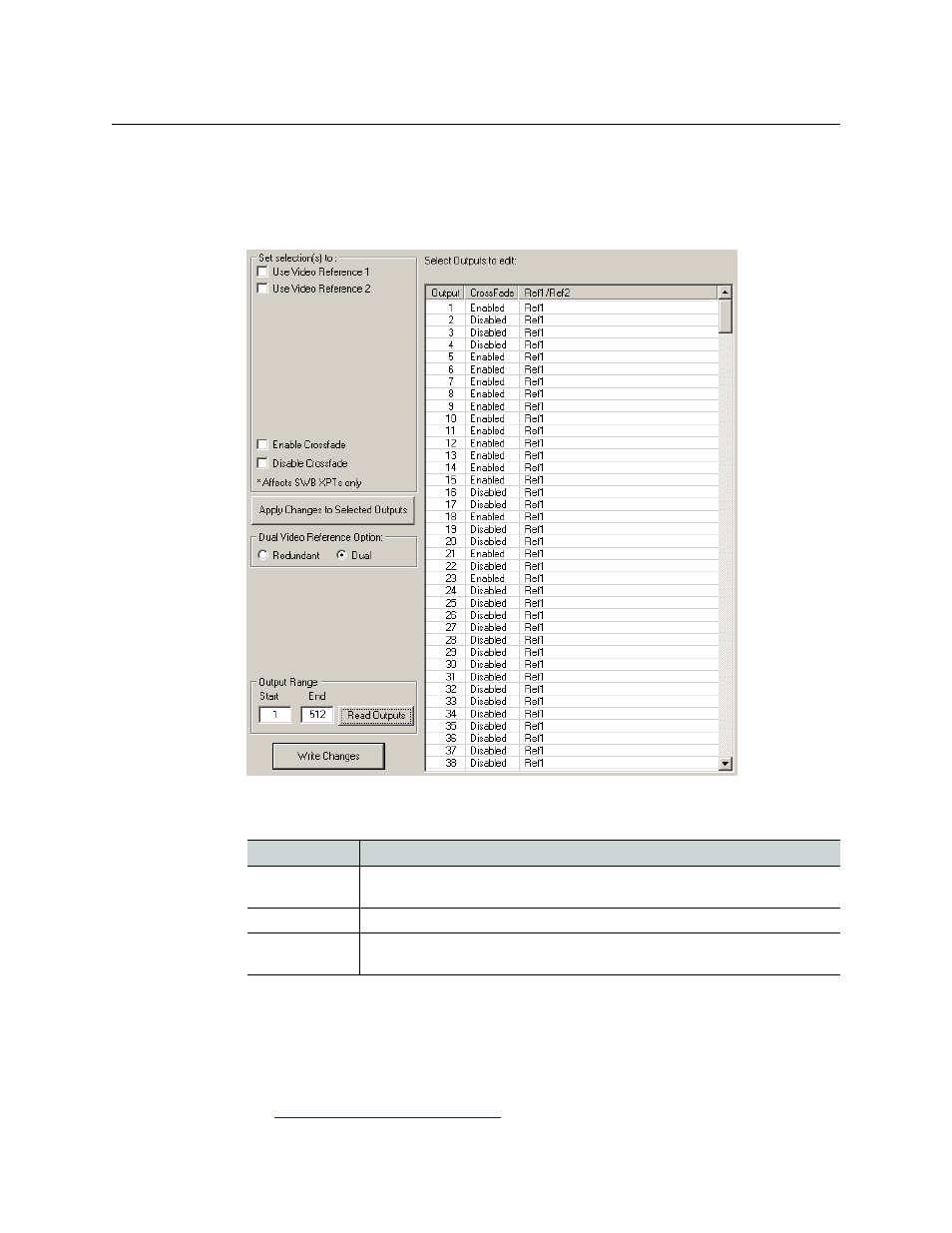
2 From the ‘Window’ menu, select ‘Switch Point Setup’. The ‘Switch Point Setup’ window
appears. Specify an output range at the bottom of the page and click Read Outputs:
Fig. 8-3: Switch Point Setup Window (NV7512, NV7512-Plus
This table describes each column in the output list:
3 In the ‘Dual Video Reference Option’ section, choose ‘Redundant’ or ‘Dual’.
‘Redundant’
—
You declare that the router will use redundant references. Both ‘VIDEO REF 1’
and ‘VIDEO REF 2’ are the same. If one fails, the other will be used as a fail-over.
‘Dual’
—
You declare that dual video references are in use. In this case, you can specify in step
5 which reference selected outputs are to use.
See
Redundant v. Dual Video Reference
Column
Description
Output
The number assigned to the signal for routing purposes. The number usually
refers to the physical port through which the signal is distributed.
Crossfade
Indicates whether crossfades (for outputs switched) are enabled or disabled.
Ref1/Ref2
Indicates whether the output uses video reference 1 or reference 2 (in dual refer-
ence mode only).