Grass Valley UniConfi NVISION Series v.2.0 User Manual
Page 59
49
UniConfig
User’s Guide
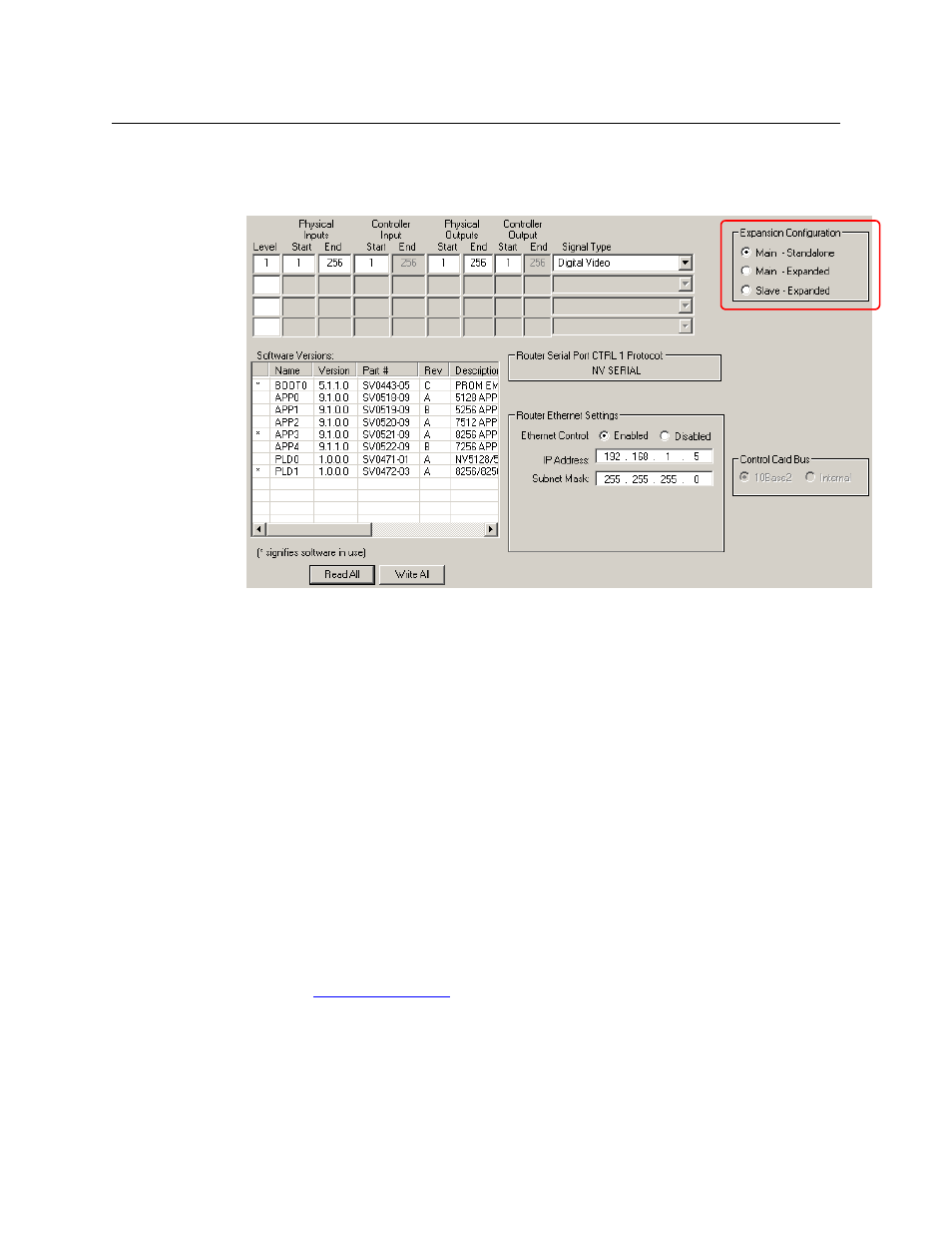
If the control card is for an expanded (or expandable) router, the router frame can be con-
nected to an identical router frame to form an expanded switching matrix. The window for
these routers displays an additional ‘Expansion Configuration’ region at the top right:
Fig. 7-4: Configuration Window (Sample, NV8256)
3 Click Read All. UniConfig populates the window with the control card’s current partition
configuration and Ethernet settings.
4 To make this a standalone router, choose the ‘Main - Standalone’ button in the expansion
settings region.
5 To set up a partition, enter values in the fields of the row representing the partition.
There are 4 rows. The first row initially contains default values for the router type.
When you place a value in the ‘Level’ field of a row, the other fields in the row become
enabled.
For the NV5100MC and NV5128, there are up to 8 partitions. Only four display at any one
time. Click Partition 1–4 or Partition 5–8 to view the corresponding levels.
For all other routers, there are up to 4 partitions.
What you should configure in the partition table is subject to your router control system and
your routing requirements and therefore beyond the scope of this document.
Choose the signal type according to the input signal format for the partition. The signal type,
in conjunction with the switch point setup, determines the rules used by the router for
switching the signals when operators execute a “take.” For information on setting the switch
point, see
6 Click Write All to writes changes to the control card.
7 Repeat steps 1 through 6 for each control card being updated.