M/e kalypso hd system, Figure 73 – Grass Valley Kalypso Installation Planning Guide User Manual
Page 78
78
Kalypso Installation Planning Guide
Section 4 — Kalypso HD Frame
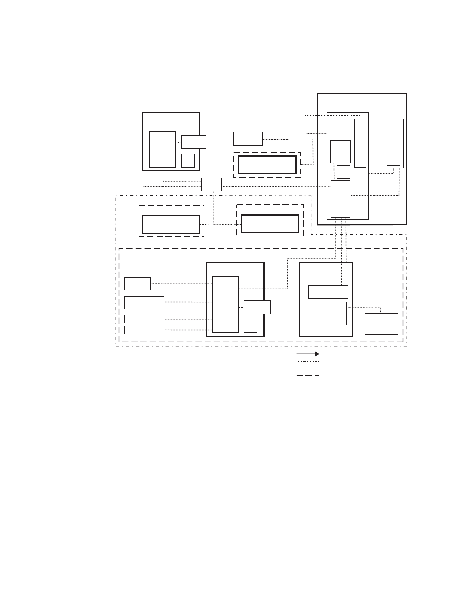
2-M/E Kalypso HD System
Figure 73. Typical 2-M/E Kalypso HD System Control
Internal Control
Still Store LAN
Facility LAN
16 GPI In
16 GPI Out
8 Serial
Tally 1-32 and
33-64 (Relay)
Kalypso HD
Video Processor Frame
2 Synchronous Serial
Control
System
CPU
Boot
Config BU
Flash
Tally
Hard
Drive
Still Store
Hard
Drive
24-Crosspoint
Remote Aux Panel
Video or Key Signal
Control Line
Suite Boundary
Control Surface Boundary
USB
USB
To networked
image sources
Ethernet
Switch
NOTES:
Control Panel, Facility, Still Store LAN: 10Base-T or 100Base-T Ethernet
Remote Aux Panels and Still Store are system options.
Point to Point Serial
Ports 1-12
RS-422/Serial Async
0619_08_80_r0
Main Control Surface
32-Crosspoint
Remote Aux Panel
Remote Control Surface #1
Kalypso Suite (Three Control Surfaces)
Remote Control Surface #2
32-Crosspoint
Remote Aux Panel
LAN
Ethernet
Switch
Shot Box
(Provided with Flush
Mount bracket.)
Menu Panel
Hard
Drive
CD-ROM
Drive
Optional Keyboard
Optional Mouse
Zip Drive
Menu
System
Processor
(Win 2000)
Optional CD-ROM
Optional
Future Satellite
Panels (1-12)
2-M/E
Main Panel
Real Time
Processor
Local Aux Panel
Additional
Menu Panel
(option)
Hard
Drive
CD-ROM
Drive
Menu
System
Processor
(Win 2000)