Typical kalypso classic system video cabling – Grass Valley Kalypso Installation Planning Guide User Manual
Page 53
Kalypso Installation Planning Guide
53
Typical Kalypso Classic System Video Cabling
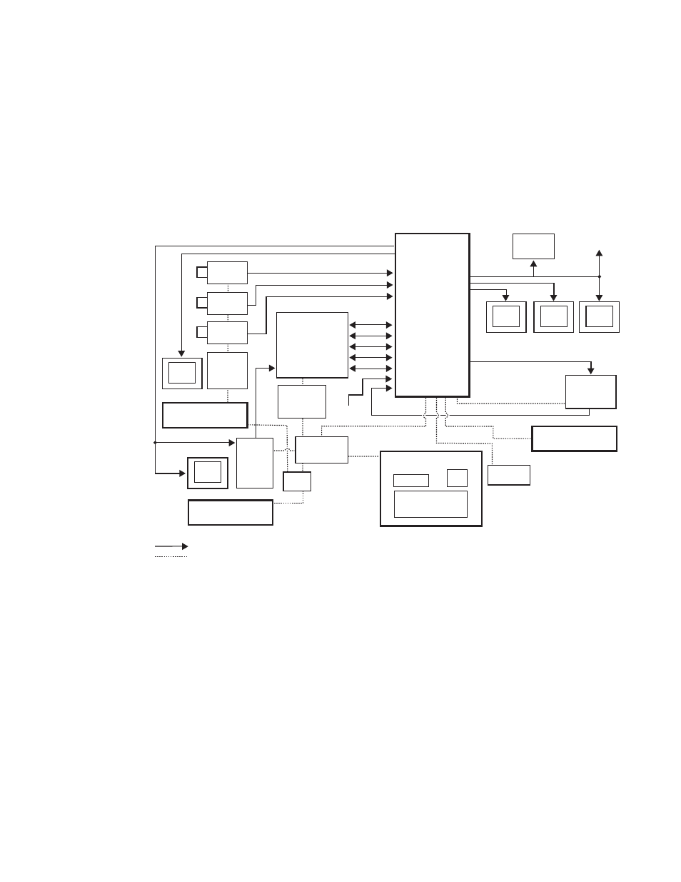
Typical Kalypso Classic System Video Cabling
Typical Kalypso Classic system connections are shown in
. Dif-
ferent video and control wiring configurations may be used to meet indi-
vidual facility requirements. All Kalypso system video inputs and outputs
are configurable. Each input can be mapped to any Kalypso panel source
select button, and any Kalypso system video signal can be mapped to any
pair of output connectors.
Figure 58. Typical Kalypso Classic System
Program
Monitor
Preview
Monitor
Other
Monitors
Program Out
Master Control/
Transmitter
Video/Key (Effects Send)
Facility
Router
Frame
Cam 1
Cam 2
Cam 3
Video
Facility Router
Control
Camera
Shader
Video/Key (Effects Return)
Synchronous Serial (CPL)
NOTE: External Effects Send
only on Kalypso Classic
Serial
Reference
Black
Aux Bus Outputs
Profile
VDR
Facility LAN
32-Crosspoint
Remote Aux Panel
Remote Control Surface #1
0618_00_17_r13
Video/Key
Kalypso Main Control Surface
Kalypso Control
Ethernet
Hub
32-Crosspoint
Remote Aux Panel
Remote Control Surface #2
Remote Control Surface #3
24-Crosspoint
Remote Aux Panel
Monitor
Monitor
Serial
LAN
Ethernet
Switch
Shot Box
Kalypso
Video
Processor
Frame
Joystick
DPM
1
VTR
1
Compatible DVEs: Krystal, GVeous/Dveous
Video or Key Signal
Control Line
Override