Grass Valley Kalypso Installation Planning Guide User Manual
Page 67
Kalypso Installation Planning Guide
67
SD Video Processor Frame Pinouts
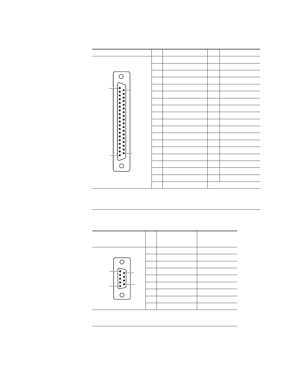
Table 18. GPI Outputs
GPI Outputs Port – J6
Pin
Function
Pin
Function
1
Chassis Ground
20
Out 1 B
2
Out 1 A
21
Out 2 B
3
Out 2 A
22
Out 3 B
4
Out 3 A
23
Out 4 B
5
Out 4 A
24
Chassis Ground
6
Out 5 A
25
Out 5 B
7
Out 6 A
26
Out 6 B
8
Out 7 A
27
Out 7 B
9
Out 8 A
28
Out 8 B
10
Chassis Ground
29
Out 9 B
11
Out 9 A
30
Out 10 B
12
Out 10 A
31
Out 11 B
13
Out 11 A
32
Out 12 B
14
Out 12 A
33
Chassis Ground
15
Out 13 A
34
Out 13 B
16
Out 14 A
35
Out 14 B
17
Out 15 A
36
Out 15 B
18
Out 16 A
37
Out 16 B
19
Chassis Ground
Notes:
Outputs are normally open relay closures between A and B.
30 volts maximum open circuit between A and B.
1 amp maximum.
Table 19. Serial Ports
RS-422 Ports
Pin
CPL Ports - J7, J8
J9, J10, J11, J12,
J13, J14, J15, J16
Serial Ports
1
Chassis Ground
Chassis Ground
2
RX -
RX -
3
TX +
TX +
4
Chassis Ground
Chassis Ground
5
Not Used
Not Used
6
Common (Ground)
Common (Ground)
7
RX +
RX +
8
TX -
TX -
9
Chassis Ground
Chassis Ground
Notes:
For Ports J9 – J16 only: The data directions specified on pins 2&3 and 7&8 as RX and TX may be
reversed in software configuration.
Pin 1
Pin 19
Pin 20
Pin 37
D-37 Female
Pin 5
Pin 6
Pin 9
D-9 Female
Pin 1