Ethernet switches and hubs – Grass Valley Kalypso Installation Planning Guide User Manual
Page 57
Kalypso Installation Planning Guide
57
Kalypso Classic System Control Cabling
Refer to
for Ethernet specifications. All Ethernet components are
supplied by the customer.
Ethernet Switches and Hubs
Kalypso components rely primarily on Ethernet switches for LAN inter-
connects. Remote Auxiliary panels may be connected directly to the
Kalypso switch, or through an Ethernet hub. A hub is required only if there
is a need to exceed 100 m (328 ft) between the Main panel and Video Pro-
cessor frame (refer to
). If a hub is used, connect hub
to switch via the Uplink port, or through a peer-to-peer (crossover) cable.
Reserve a port on Kalypso’s Ethernet switch if you will be utilizing an
existing hub or switch (e.g., Omnibus LAN) (see
).
Note
The number and type of components in your Kalypso system determines the
size of the switch (number of ports) required. Refer to the following examples
of system topography and the accompanying worksheet to determine the
number of ports required for your system.
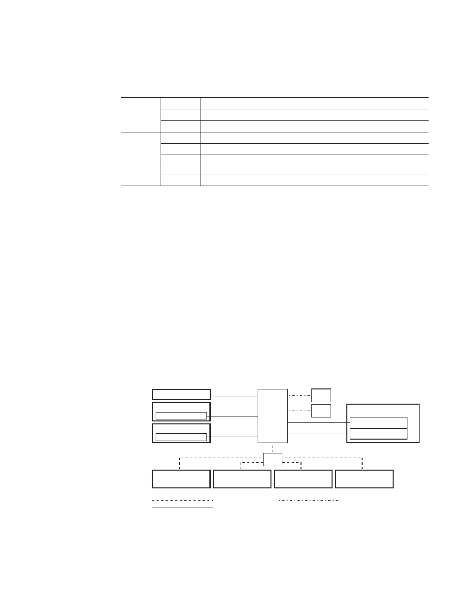
Figure 61. Example Topography Requiring an Eight Port Ethernet Switch
Table 14. Kalypso Classic System Ethernet Specifications
Cables
Type
a
a
100Base-T required for core Kalypso system operation. 10Base-T used for 32-Crosspoint Remote Aux panels.
100Base-T and 10Base-T compatible. Category 5 or 6 cable, 8 conductor twisted pair.
Connectors
RJ-45 male connector at each end of cable.
Length
b
b
Use a hub when necessary to exceed maximum cable runs.
100Base-T: 100 m (328 ft) maximum. 10Base-T: 300 m (984 ft) maximum.
Switch
Speed
Dual: 10 and 100 Mb
Ports
RJ-45 auto-negotiating 10/100 Mb; number of ports required is dependent upon system size.
Unmanaged
Recommended. Configuration is not required, but does not provide remote monitoring capa-
bility.
Managed
May be used. Requires configuration, but offers remote monitoring capability.
Ethernet
Hub1
32-XPT Remote
Aux Panel
(Option)
32-XPT Remote
Aux Panel
(Option)
32-XPT Remote
Aux Panel
(Option)
32-XPT Remote
Aux Panel
(Option)
Profile
Profile
0619_02_01_r5
Video Processor Frame
Control System Facility LAN
Still Store
8 Port
Ethernet
Switch
1 Use hubs to exceed 100 m (328 ft.) cable limitations.
10BaseT Facility LAN
100BaseT Facility LAN
10/100BaseT Facility Intranet
Local Aux Panel
Main Panel
Real Time Processor
Menu Panel
Windows Processor