Removable media drives, M/e and 2-m/e main panel installation – Grass Valley Kalypso Installation Planning Guide User Manual
Page 17
Kalypso Installation Planning Guide
17
4-M/E and 2-M/E Main Panel Installation
storage. An optional Remote Aux panel can also be added for Aux bus con-
trol. Though the 1-M/E Main panel has only one M/E control bank, it can
be delegated to control any of the M/Es of a 2 or 4-M/E Kalypso system.
Removable Media Drives
Two removable media drives are standard components of a Kalypso 4-M/
E or 2-M/E system. Included are a CD-ROM drive (installed inside the
Menu panel), and an external USB 250 MB Zip drive (which connects to the
Menu panel). No special mounting brackets or specific placement is
required for the Zip drive; placement is restricted only by USB cable length.
An external USB CD-ROM drive is provided with the Menu panel Flush
Mount kit, as flush mount installation may block access to the drive inside
the Menu panel. Other customer supplied USB drives can be added.
4-M/E and 2-M/E Main Panel Installation
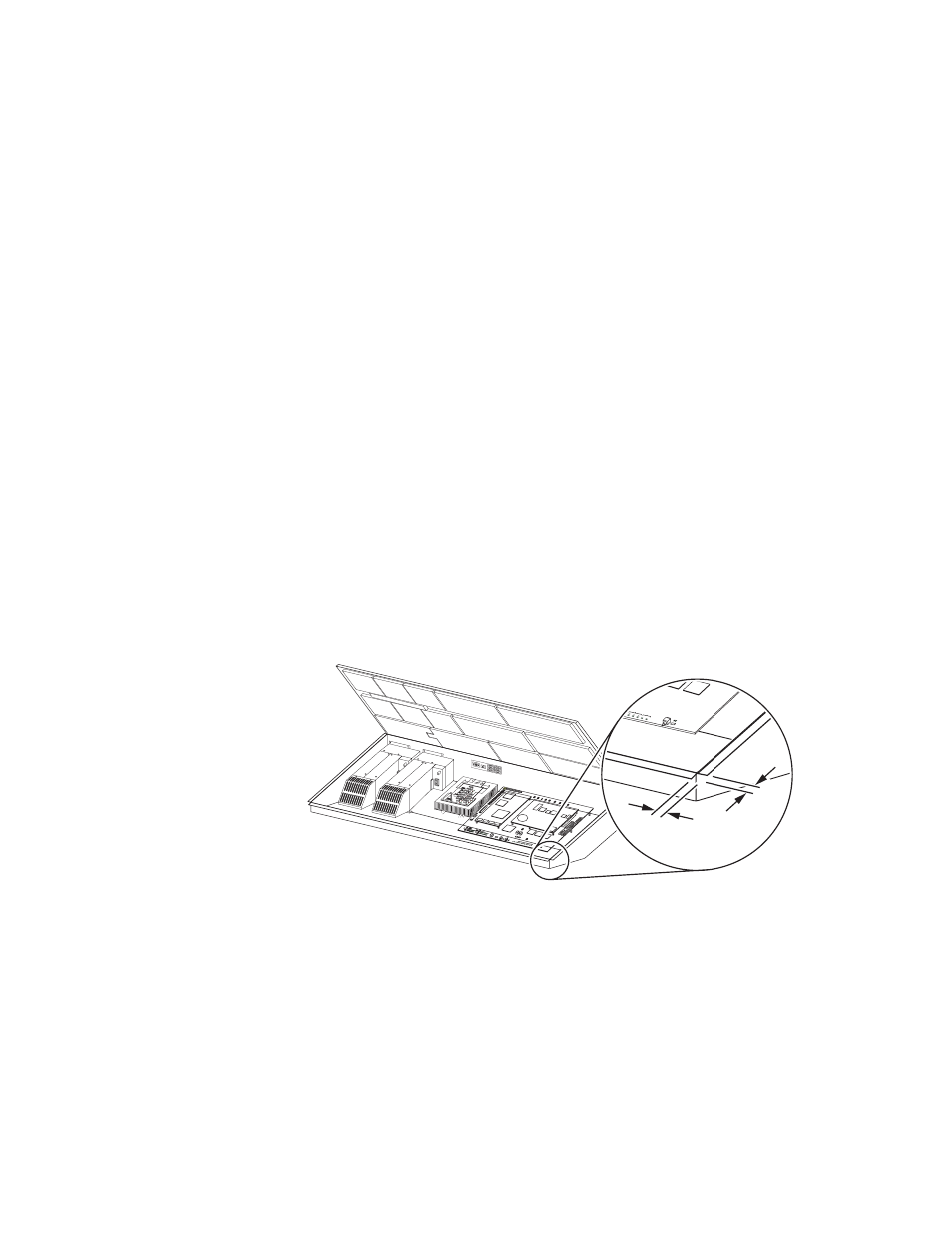
4-M/E and 2-M/E Main panel installations require careful attention to the
console support structure and the console cutout dimensions necessary to
accommodate the mounting flanges located on the front and sides of the
tub (
).
Figure 5. Mounting Flanges
CAUTION The 4-M/E Main panel weighs approximately 86 kg (189 lb) and the 2-M/E
Main panel weighs approximately 63 kg (138 lb). Prior to installation, ensure
that your console is structurally capable of supporting the Main panel.
The 4 and 2-M/E Main panels are designed to be flush mounted in a con-
sole, but it may also be surface mounted.
provides installation
details for both flush mount and surface mount installations. Refer to 4-M/
E Main Panel
for dimensions and other information specific to the
4-M/E Main panel, or 2-M/E Main Panel
to the 2-M/E Main panel.
0619_07_52_r0
SATELLIT
E PORTS
TRANSM
IT
RECEIV
E
8 8 8
8 8 8
8 8
TRANSM
IT
GP8
GP7
GP6
GP5
GENERA
L
PURPO
SE
LEDS
GP4
GP5
GP1
GP0
RECEIV
E
SATEL
LITE P
ORTS
FAULT
INIT
RUN
XMT
C119
RCV
LINK
RTP/C
ONTR
OL PA
NEL L
AN
ACTIV
ITY
COLN
C29
3.3V
R151
R152
POW
ER SU
PPLIE
S
MENU
PROC
ESSO
R
RESE
T
R153
5V
12V
SCSI
HARD
DISK
5 6
7
8
9
0
1
2
34
T
RUN
XMT
C119
RCV
LINK
RTP/C
ONTR
OL PA
NEL L
AN
ACTIV
ITY
COLN
C29
3.3V
R151
R152
POW
ER SU
PPLIE
S
MENU
PROC
ESSO
R
RESE
T
R153
5V
12V
SCSI
HARD
DISK
0.43 in.
11 mm