Figure 46, Crosspoint remote aux connections – Grass Valley Kalypso Installation Planning Guide User Manual
Page 41
Kalypso Installation Planning Guide
41
Optional System Components
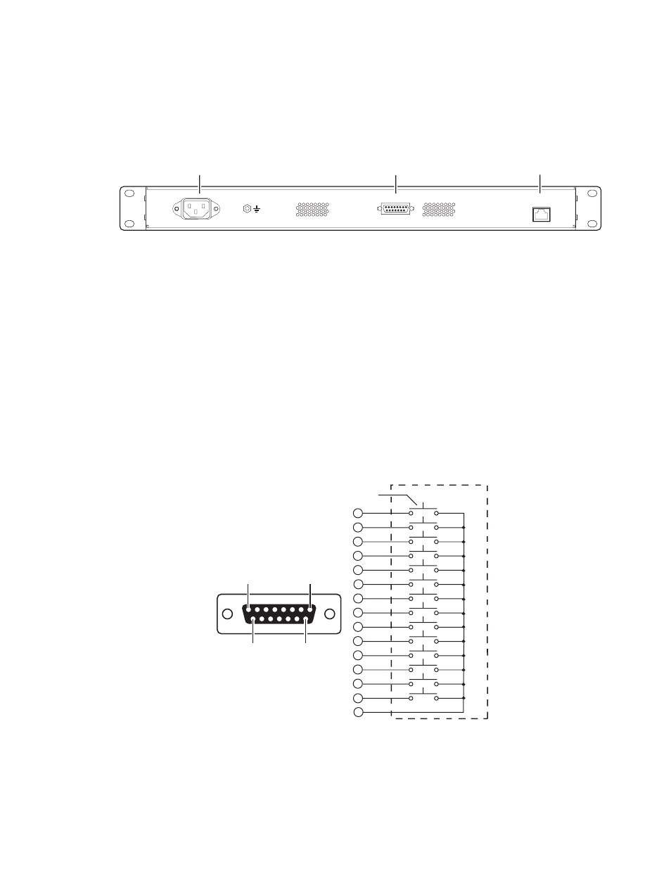
32-Crosspoint Remote Aux Connections
The 32-Crosspoint Remote Aux rear panels have connectors for AC power,
LAN, and Camera Joystick Override (
Figure 46. KAL-32AUX1 (1 RU), Rear View
Note
The rear panel layout is the same for both KAL-32AUX panels.
AC Power
– The 32-Crosspoint Remote Aux panels have internal power sup-
plies which connect directly to facility AC power by supplied line cords.
LAN
– The 32-Crosspoint Remote Aux panels employ Ethernet network con-
figuration. Refer to Ethernet Switches and Hubs
system topography.
Camera Joystick Override
– A user fabricated cable, external switch, and a 15-
pin D connector are required to implement camera joystick override. Use
shielded cable and connect the shield to the metal connector shell when
fabricating the joystick override cable. Refer to
wiring.
Figure 47. KAL-32AUX Joystick Override Connector Cable Wiring
RATED CURRENT: 0.35 A
CAMERA JOYSTICK
OVERRIDE
FREQUENCY: 47-440 Hz
RATED VOLTAGE RANGE: 85-260 VAC
LAN
0619_04_59_r2
LAN
Camera Joystick Override
AC Power
Common
0619_04_62_r3
1
2
3
4
6
7
8
5
9
10
11
12
13
15
14
Pin 1
Pin 15
Pin 9
D-15 Male
Joystick Override
Connector
(wiring side)
Pin 8
Momentary Contact Switches