Typical kalypso hd system video cabling – Grass Valley Kalypso Installation Planning Guide User Manual
Page 76
76
Kalypso Installation Planning Guide
Section 4 — Kalypso HD Frame
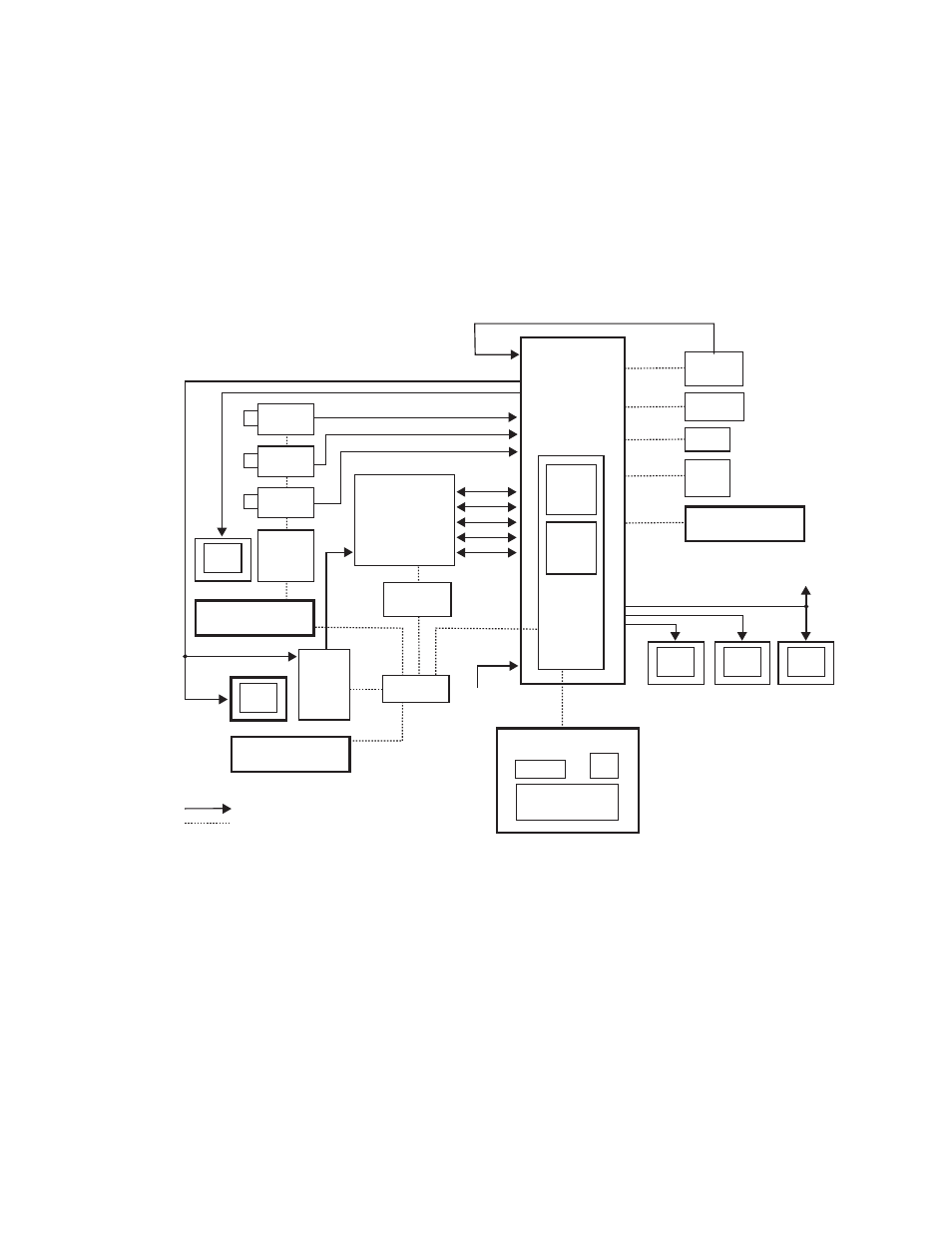
Typical Kalypso HD System Video Cabling
Typical Kalypso HD system connections are shown in
. Different
video and control wiring configurations may be used to meet individual
facility requirements. All Kalypso system video inputs and outputs are
configurable. Each input can be mapped to any Kalypso panel source select
button, and any Kalypso system video signal can be mapped to any pair of
output connectors.
Figure 71. Typical Kalypso HD System
Serial Ports
(8 total)
Program Out
Kalypso
HD Video
Processor
Frame
HDTV Program
Monitor
HDTV Preview
Monitor
Other HDTV
Moni tors
Master Control/
Transmitter
Facility
HD Router
Frame
HDTV
Cam 1
HDTV
Cam 2
HDTV
Cam 3
Video
Video
Facility Router
Control
Camera
Shader
Serial
Serial
Serial
Serial
Serial
SD or HD
Reference
Aux Bus Outputs
Profile
XP
32-Crosspoint
Remote Aux Panel
Remote Control Surface #1
0619_08_78r0
Video/Key
Kalypso Main Control Surface
Kalypso Control
Ethernet
Switch
32-Crosspoint
Remote Aux Panel
Remote Control Surface #2
Remote Control Surface #3
24-Crosspoint
Remote Aux Panel
HDTV Monitor
HDTV Monitor
Shot Box
Joystick
VTR
Video or Key Signal
Control Line
Override
Ethernet
LAN
Switch
8 Ports
(6 external/
2 internal)
Still
Store
(3 LAN Ports)
(1 LAN Port)
Editor
Serial
Tally
Frame
CPU
1 LAN Port
(internal)
1 LAN Port
(internal)