Emergency bypass frame – Grass Valley Kalypso Installation Planning Guide User Manual
Page 62
62
Kalypso Installation Planning Guide
Section 3 — Kalypso Classic Frame
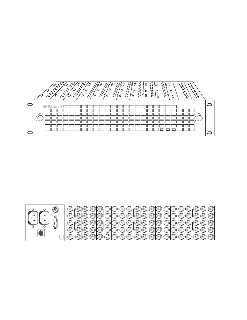
Emergency Bypass Frame
The 2 RU Emergency Bypass frame (
) fits a standard 19 in. (483
mm) equipment rack (See
for dimensions). Behind
the front cover are ten slots for modules, plus one control slot and two slots
for power supplies. The standard Kalypso Emergency Bypass option only
uses two of these slots, typically slot 7 for the Relay Module and slot 8 for
the Keyer module.
Figure 66. 8900TF Frame, Front View
The forced-air system has a front cover equipped with three fans for air cir-
culation. The fan speed varies with the ambient frame temperature. Fan
speed control voltage is generated on the Kalypso Emergency Bypass
Frame Monitor module and can be disabled so that the fan runs at
maximum speed only.
The right rear of the frame (
) includes ten groups of ten connectors
(corresponding to the ten frame slots), which are used for input/output
functions for inserted modules.
Figure 67. 8900TF Frame, Rear View
The power and communication section at the left rear of the frame provides
RS-422 communications (the connector is labeled RS-232, but is RS-422
when the Kalypso Emergency Bypass Frame Monitor module is installed),
AC power plug connections, and SMPTE Alarm BNC (J101) for fault
reporting. The Ethernet connector is not used with the Kalypso Emergency
Bypass option.
0619_05_03_r0
LOCK
LOCK
FAULT
PS1
PS2
8900 Series
J1
DA10
J1
DA10
0619_05_04_r1
J1
J2
J3
J4
J5
J6
J7
J8
J9 J10
IN
1
J2
J4
J6
J8
J1
J2
J3
J4
J5
J6
J7
J8
J9 J10
IN
3
J1
J2
J3
J4
J5
J6
J7
J8
J9 J10
IN
5
J1
J2
J3
J4
J5
J6
J7
J8
J9 J10
IN
2
J1
J2
J3
J4
J5
J6
J7
J8
J9 J10
IN
7
J1
J2
J3
J4
J5
J6
J7
J8
J9 J10
IN
9
J1
J2
J3
J4
J5
J6
J7
J8
J9 J10
IN
4
J2
J4
J6
J8
J1
J2
J3
J4
J5
J6
J7
J8
J9 J10
IN
6
J2
J4
J6
J8
J1
J2
J3
J4
J5
J6
J7
J8
J9 J10
IN
8
J2
J4
J6
J8
J1
J2
J3
J4
J5
J6
J7
J8
J9 J10
IN
10
O
U
T
O
U
T
O
U
T
O
U
T
O
U
T
O
U
T
O
U
T
O
U
T
O
U
T
O
U
T
SMPTE
ALARM
J101
RS232
J102
ETHERNET
J103
J1
J2