Kalypso hd system control cabling, M/e kalypso hd system – Grass Valley Kalypso Installation Planning Guide User Manual
Page 77
Kalypso Installation Planning Guide
77
Kalypso HD System Control Cabling
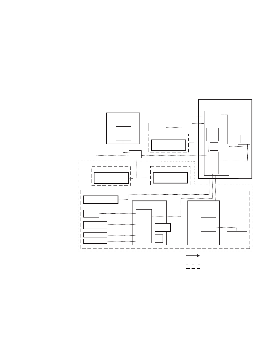
Kalypso HD System Control Cabling
The Kalypso HD system uses Ethernet, serial, parallel, and SCSI control.
Tally and GPI control are also available (see
). Refer
for a list of supplied cables.
4-M/E Kalypso HD System
Figure 72. Typical 4-M/E Kalypso HD System Control
Internal Control
Still Store LAN
16 GPI In
16 GPI Out
8 Serial
Tally 1-32 and
33-64 (Relay)
Kalypso HD
Video Processor Frame
2 Synchronous Serial
Control
System
CPU
Boot
Config BU
Flash
Tally
Hard
Drive
Still Store
Hard
Drive
Remote Control Surface #3
24-Crosspoint
Remote Aux Panel
Video or Key Signal
Control Line
Suite Boundary
Control Surface Boundary
USB
USB
To networked
image sources
Ethernet
Switch
NOTES:
Control Panel, Facility, Still Store LAN: 10Base-T or 100Base-T Ethernet
Remote Aux Panels and Still Store are system options.
Point to Point Serial
Ports 1-12
RS-422/Serial Async
0619_08_79_r0
Local Aux Panel
Main Control Surface
32-Crosspoint
Remote Aux Panel
Remote Control Surface #1
Kalypso Suite (Four Control Surfaces)
Remote Control Surface #2
32-Crosspoint
Remote Aux Panel
LAN
Ethernet
Switch
Shot Box
(Provided with Flush
Mount bracket.)
Menu Panel
Hard
Drive
CD-ROM
Drive
Optional Keyboard
Optional Mouse
Zip Drive
Menu
System
Processor
(Win 2000)
Optional CD-ROM
Optional
Future Satellite
Panels (1-12)
4-M/E
Main Panel
Real Time
Processor
1-M/E
Main Panel
(option)
Real Time
Processor