Ear of the main panel lid, Figure 7 – Grass Valley Kalypso Installation Planning Guide User Manual
Page 19
Kalypso Installation Planning Guide
19
4-M/E and 2-M/E Main Panel Installation
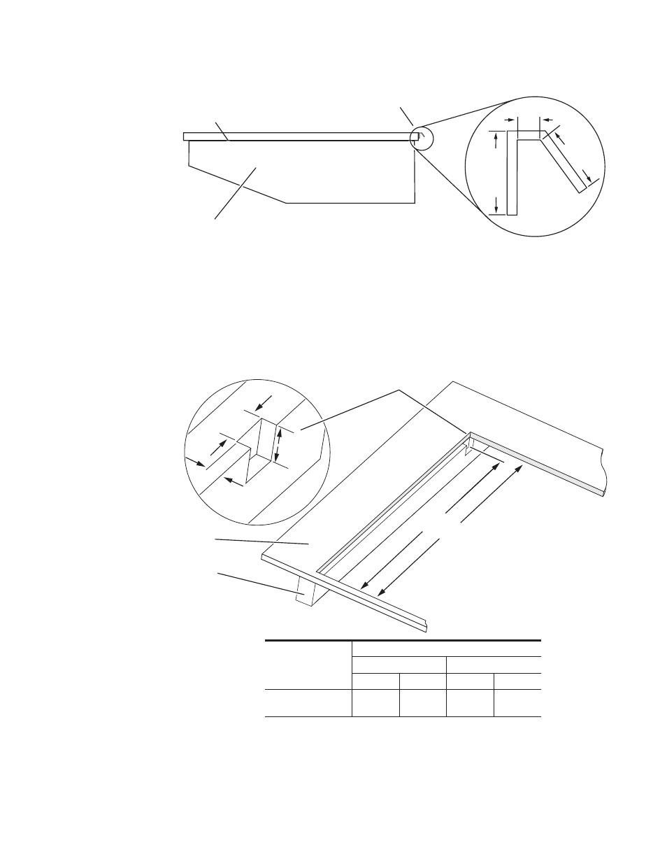
Figure 7. Main Panel with Attached Cosmetic Bracket, Side View
If you choose to use the cosmetic bracket and your Main panel installation
has a console support structure similar to that shown in
, it will be
necessary to cut notches in the support members at the left and right rear
corners of the console cutout (see the notch dimensions in
). This
enables the Main panel lid to clear the support structure upon opening.
Figure 8. Support Member Notch Dimensions
0619_05_02_r0
Cosmetic Bracket
Main Panel Lid
Main Panel Tub
.69 in.
.69 in.
17.53 mm
17.53 mm
.27 in. / 6.86 mm
.27 in. / 6.86 mm
00.60 in.
00.60 in.
15.24 mm
15.24 mm
0.69 in.
18 mm
0.27 in. / 7 mm
0.60 in.
15 mm
00619_05_05_r2
A
B
13 mm / 0.5 in.
25 mm
1.0 in.
25 mm
1.0 in.
Console
Control Panel
Console Cutout
Notch
Support Member
Front
Back
Mounting Option
Dimensions
A
B
a
a
Console cutout dimension.
2-M/E
4-M/E
2-M/E
4-M/E
Flush Mount
19.09 in.
(485 mm)
24.06 in.
(611 mm)
20.09 in.
(510 mm)
25.06 in.
(637 mm)