Cabling – Grass Valley Kalypso Installation Planning Guide User Manual
Page 44
44
Kalypso Installation Planning Guide
Section 2 — Kalypso Control Surfaces
Cabling
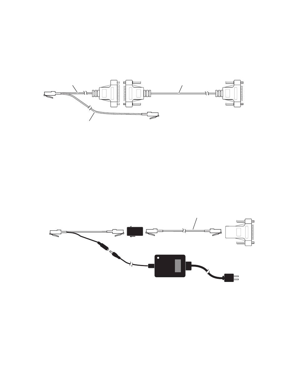
The provided cables connect the Main panel, Shot Box, and Video Pro-
cessor frame as shown in
. Power passes from the Main panel to
the Shot Box over this cable.
Figure 51. Provided Shot Box Cables and Connections
Optional Satellite Panel Extension
If the Shot Box is to be placed more than 3 m (10 ft)
from the Main panel, an
optional Satellite Panel extension kit is available, permitting installation up
to 100 meters away. The kit consists of a Y-cable (to separate the communi-
cation path from the power path), a separate power supply, and two
adapters. A Cat-5 extension cable of the desired length is to be provided by
the end user. The Satellite Panel extension kit cabling replaces any existing
Shot Box cabling (
).
Figure 52. Shot Box Panel Extension Cabling, Editor Port Connection
Male
To Video Processor
Frame Editor Port
16 m (52 ft)
To Shot Box
To Main Panel
Satellite Port
3 m (10 ft)
0619_05_07_r2
0.3 m (1 ft)
Female
Male
To Video Processor
Frame Editor Port
User Supplied Cat-5 Cable
100 meter maximum length
8159_00_01_r1
To Shot Box
Option Kit
Y-Cable
Plug
J2
9-Pin to RJ-45
Adapter
RJ-45
Barrel
Adapter
Power
Supply
To AC
Source