Local aux panel installation, Figure 22. local aux panel dimensions, Figure 23. local aux panel connections – Grass Valley Kalypso Installation Planning Guide User Manual
Page 26
26
Kalypso Installation Planning Guide
Section 2 — Kalypso Control Surfaces
Local Aux Panel Installation
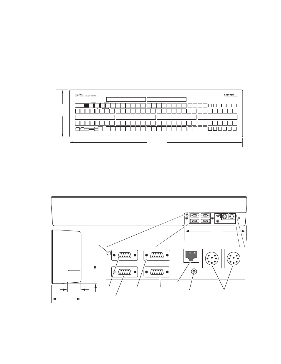
The Local Aux panel (
) provides control of Kalypso System Aux
buses, the Emergency Bypass system, Still Store source selection, switched
preview, gang roll control, and router source selection. The Local Aux Panel
is integrated into the design of the 2-M/E Main panel, so a separate Local
Aux panel is not provided with 2-M/E systems.
Figure 22. Local Aux Panel Dimensions
Ports located on the rear of the Local Aux panel (
) provide connec-
tions to the Kalypso Main panel. The Kalypso system may also be config-
ured with several types of Remote Aux panel. Refer to Remote Aux Panels
for more information on these panels.
Figure 23. Local Aux Panel Connections
Bypass Active
Assign
Emergency
Bypass
Select
Source
Key
2
Key
1
Bypass
Delegate
Aux
1
Aux
2
Aux
3
Aux
4
Aux
8
Aux
5
Aux
6
Aux
7
Aux
9
Aux
10
Aux
11
Aux
12
M / E
1
PGM
PST
Near
Side
Un
Shift
Key
Split
Shift
Hold
M / E
2
M / E
3
Prev
Page
Gang
Select
Router
Assign
Next
Page
Aux
1
Aux
2
Aux
3
Aux
4
Aux
5
Aux
11
Aux
12
Still
Store
M / E
1
M / E
2
M / E
3
PGM
PST
Hold
Near
Side
Un
Shift
Key
Split
Shift
Far
Side
Bypass
Enable
Aux
13
Still
Store
PVW
Pri
Aux
6
Aux
7
Aux
8
Aux
13
PVW
Pri
Aux
9
Aux
10
26.3 in.
668 mm
7.2 in.
183 mm
0619_00_10_r6
1.8 in.
46 mm
1.8 in.
46 mm
3.9 in.
99 mm
8.4 in.
213 mm
Bottom
View
Side
View
Without
Mounting
Bracket
Spare
Emergency
Bypass
Mixer
Diagnostic
Emergency
Bypass
Router
LAN
0618_03_127_r2
Main and Redundant
DC Power In
Local Aux Panel
Boot Dial
(recessed)
Local Aux Panel
Reset Button