Grass Valley Kalypso Installation Planning Guide User Manual
Page 39
Kalypso Installation Planning Guide
39
Optional System Components
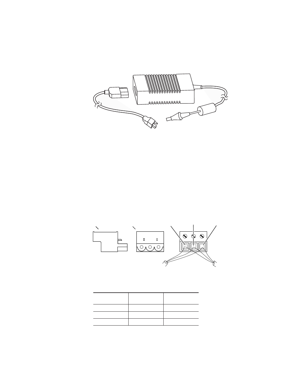
Power Supply
– The 24-Crosspoint Remote Aux panel power supply
(
) should be securely fastened to a horizontal surface or attached
to a support inside the equipment rack. Verify that the power supply cord
reaches the 24-Crosspoint Remote Aux Control panel and the AC source.
Figure 41. KAL-24AUX Power Supply
Communications Bus
– The communications bus cable connector shipped with
each panel must be attached to the supplied cable or a user fabricated cable
(refer to
). The supplied cable is 50 m (164 ft) long and has a pre-
wired 9-pin D connector on one end.
If fabricating a cable, use a shielded twisted pair cable such as Belden 8451
and refer to
for wiring connections. The total length of cable in a 24-
Crosspoint Remote Aux panel daisy-chain cannot exceed 320 m (1000 ft).
Allow enough cable to reach each control panel connector, plus about 1 m
(approximately 3 ft) extra.
Figure 42. KAL-24 AUX Communications Bus Connector Cable Wiring
Table 8. Cable Polarity
Panel
Connector
D-Connector
Pins
Factory Supplied
Cable
+ (Plus)
3 and 7
Red
- (Minus)
2 and 8
Black
Shield
9
Shield
0619_04_63_r1
0619_04_66_r0
To Pin 9 of
D Connector
(SHIELD)
To Pins 2 and 8 of
D Connector (–)
To Pins 3 and 7 of
D Connector (+)
To Next Panel
(If Any)
Side View
Connector-end
View
From Switcher or
Previous Panel