Power cabling, M/e systems – Grass Valley Kalypso Installation Planning Guide User Manual
Page 28
28
Kalypso Installation Planning Guide
Section 2 — Kalypso Control Surfaces
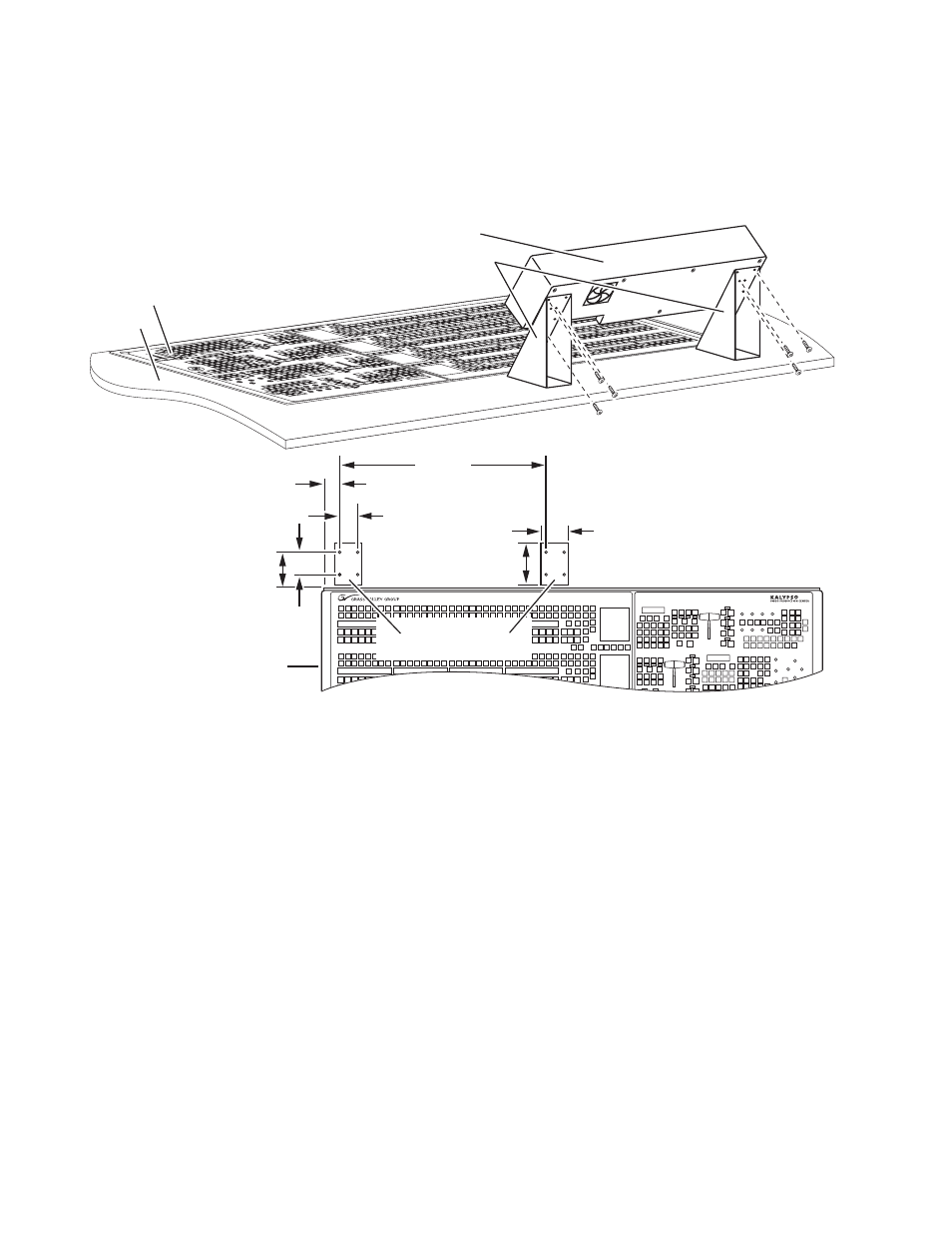
provides guidance for mounting the Local Aux panel using free-
standing console brackets so that its Source Selection buttons align with
those on the 4-M/E Main panel.
Figure 26. Recommended Bracket Placement for Console Mounting Local Aux Panel
Power Cabling
4-M/E Systems
Normally, the Local Aux panel receives power from the Main panel via a
cable connected between the two panels. If the Main panel has two power
supplies, there is already redundant power protection. It is also possible to
install an external power supply (see
) for additional redundancy
that connects to the Redundant DC Power In connector on the Local Aux
panel (see
). If desired, two separate external power supplies can
be connected to the Local Aux panel. This eliminates the need to connect a
power cable from the Main panel to the Local Aux panel.
2-M/E Systems
Local Aux control is integrated into the 2-M/E Main panel, but it has a sep-
arate processor. It is powered by a direct connection inside the Main panel.
If the Main panel has two power supplies, there is already Local Aux
0619_00_46_r0
3.91 in.
99 mm
Measurements
referenced to left
rear corner of tub.
Main Panel
4.68 in.
119 mm
2.5 in.
64 mm
2.0 in.
51 mm
1.05 in.
27 mm
3.0 in.
76 mm
22.73 in.
577 mm
Local Aux Panel
Console Bracket Footprint
Grass V
Gra
ss V
alley
alle
y GroupG
rou
p
Kal
yp
so
Kal
yp
so
0619_00_45_r1
Local Aux Panel
Fixed Freestanding
Console Brackets
Console
Main Panel