Available mounting brackets, Figure 30 – Grass Valley Kalypso Installation Planning Guide User Manual
Page 31
Kalypso Installation Planning Guide
31
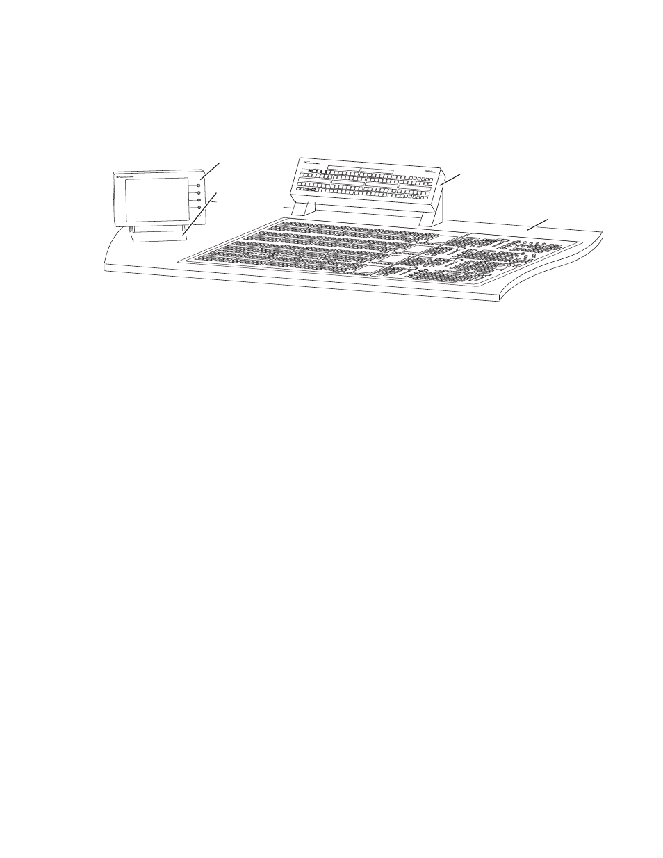
Menu Panel Installation
the area for better viewing of monitors beyond the Main panel. When con-
sidering mounting options, remember that the optimum Menu panel
viewing angle is 90 degrees in both the horizontal and vertical planes.
Figure 30. Recommended Menu Panel Mounting Location
CAUTION When finalizing the location of the Menu panel, be sure to open the Main
panel lid and check for sufficient clearance between the Menu panel and the
Main panel components.
Available Mounting Brackets
When ordering your system, you will specify the type of Menu panel
mounting bracket. Three different mounting brackets are available to
provide a wide variety of installation options. One bracket type is included
with each system, and one additional bracket of your choice is also
included:
•
Adaptable Mounting bracket (always included), and choose either
•
Adjustable Freestanding Console bracket,
- or -
•
Flush Mount kit.
If a preference is not given, the Flush Mount kit will be shipped.
CAUTION All Menu panel mounting holes are tapped 10-32. Do not penetrate the case
more than 0.24 in. / 6.10 mm.
Bypass Active
Assign
Emergency
Bypass
Select
Source
Bypass
Enable
Key
On
Source 2
Key
On
Source 1
Bypass
Delegate
Aux
1
Aux
2
Aux
3
Aux
4
Aux
8
Aux
5
Aux
6
Aux
7
Aux
9
Aux
10
Aux
11
Aux
12
PVW
Still
Store
1
Still
Store
2
M / E
1
PGM
PST
Near
Side
Un
Shift
Key
Split
Shift
Hold
M / E
2
M / E
3
Prev
Page
Gang
Select
Router
Assign
Next
Page
Aux
1
Aux
2
Aux
3
Aux
4
Aux
5
Aux
6
Aux
7
Aux
8
Aux
9
Aux
10
Aux
11
Aux
12
Still
Store
1
Still
Store
2
PVW
M / E
1
M / E
2
M / E
3
PGM
PST
Hold
Near
Side
Un
Shift
Key
Split
Shift
Far
Side
Menu Panel
Adjustable
Freestanding
Console Bracket
Local Aux Panel
Main Panel
8162_00_06_r1
Console