M/e main panel – Grass Valley Kalypso Installation Planning Guide User Manual
Page 20
20
Kalypso Installation Planning Guide
Section 2 — Kalypso Control Surfaces
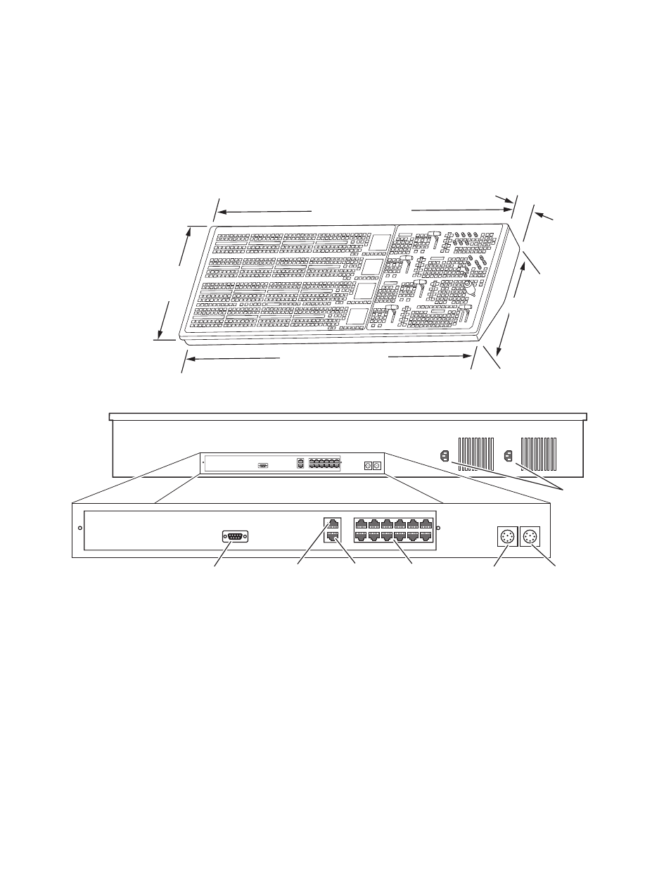
4-M/E Main Panel
4-M/E Main panel options include a redundant power supply and Source
ID displays for M/E 1, 2, and 3. (Source ID displays are standard on PGM/
PST and on the Local Aux panel.) Refer to
through
panel dimensions and connector layout.
Figure 9. 4-M/E Main Panel Dimensions
Figure 10. 4-M/E Main Panel, Rear View
CAUTION Regardless of mounting method or cutout dimensions, ensure that there is
at least 152 mm (6 in.) of clear space at the rear of the Main panel below the
mounting surface for proper cable clearance and air flow. Allow an extra
203 mm (8 in.) to 254 mm (10 in.) of mounting surface behind the Main
panel for peripheral components (e.g., Local Aux panel).
24.58 in.
624 mm
(lid)
55.5 in. / 1410 mm (lid)
54.65 in. / 1388 mm (tub)
23.56 in.
598 mm
(tub)
7.44 in.
189 mm
(tub to top
of lid)
0619_00_30_r1
Menu Panel
Power
Local Aux Bus
Power
Panel
Diagnostic
Panel
LAN
Satellite Control
Panels (12)
Not
Used
AC In
8162_00_02_r0