Grass Valley Kaleido-X (7RU) v.7.70 User Manual
Page 72
60
Kaleido-X (14RU) Expansion
Expanding EXISTING Kaleido-X Frames
conditions (the Normal mode alarm should be green in all cases). Take note of the
Ethernet settings for each frame.
2 Power down both frames.
3 Check the pins on the expansion card connectors to make sure they are straight
(inserting a card with bent pins can damage the card).
4 Gently but firmly, slide one expansion card into the slot labelled OUTPUT D / EXP of the
Kaleido-X that will be designated Frame A.
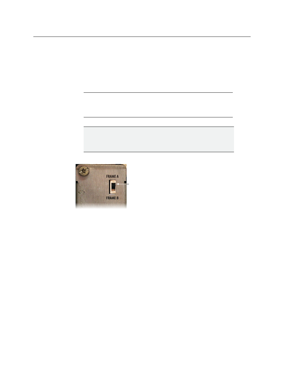
5 Set the Frame ID switch on the rear panel to the Frame A position.
6 Gently but firmly, slide the other expansion card into the slot labelled OUTPUT D / EXP
of the Kaleido-X that will be designated Frame B.
7 Set the Frame ID switch on the rear panel to the Frame B position.
8 Connect the two expansion cards using the expansion cables:
• EXP LINK 1 on Frame A to EXP LINK 1 on Frame B
• EXP LINK 2 on Frame A to EXP LINK 2 on Frame B
Note:
Be careful to install the KXO-EXP-R rear panel in the matching
location at the rear of the frame. The KXO-EXP-F card and its rear panel can
be installed in any order. See
Card Installation and Replacement
for more information.
IMPORTANT
Make sure that there is a KXO card in Slot C of Frame A.
This card will act as the master for the expansion frame. Another output card
may become the master.
Frame ID switch