Gpi circuits – Grass Valley Kaleido-X (7RU) v.7.70 User Manual
Page 36
24
Kaleido-X (7RU) Installation
GPI/Genlock Card
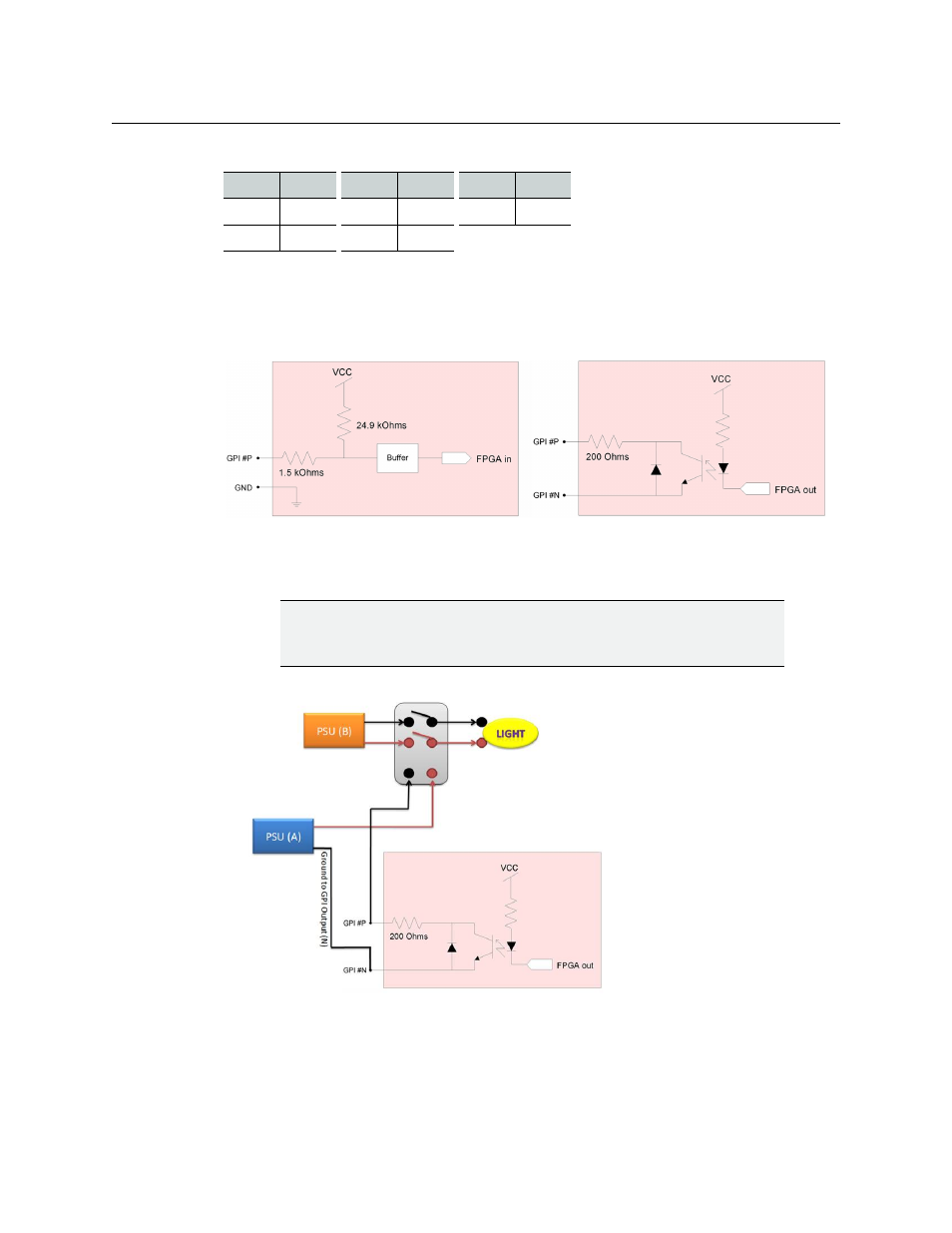
GPI Circuits
The individual GPI contacts are reconfigurable as either inputs or outputs. For interfacing
purposes, the input and output circuit configurations are as shown in the following
diagrams:
You should ensure your GPI physical connections are well established. In the following
example, the goal is to trigger a relay and light up a light.
To facilitate cabling of the GPI inputs and outputs, a terminal block adapter is available
separately (order code KXA-TBA-G). The GPI Terminal Block Adapter accommodates up to
24 terminal block connections using positive and negative terminal connections. Each
column on the terminal block has 6 positive and 6 negative terminal connections that
correspond to each pin position. Negative pins (labelled with an N) on the Terminal Block
16
1P
33
2P
50
3P
17
GND
34
GND
CAUTION
In the example below, make sure your P and N connections are in the
proper polarity otherwise your GPI output will always be in the ON state.
Pinout for GPI A, GPI B and GPI C connectors (continued)
Pin
Signal
Pin
Signal
Pin
Signal
GPI configured as INPUT
GPI configured as OUTPUT