Rear panel connections, Head 1, Head 2 – Grass Valley Kaleido-X (7RU) v.7.70 User Manual
Page 29: Control, Panel (see, Below
17
Kaleido-X (7RU)
Hardware Description & Installation Manual
• KXO-Dual3: For a KXO-Dual3 card, the scan format is set with the associated displays’
configuration, in XEdit. Refer to the Rooms chapter, in the Kaleido-X User’s Manual, for
details.
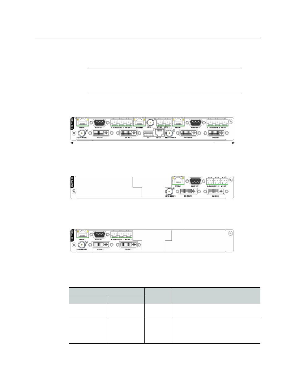
Rear Panel Connections
The rear panel layout is divided into three areas: Head 1, Head 2, and Control.
Head 1
The connectors located at the top of the rear panel (right-hand side when the card is
horizontal and you can read the connector labels normally) are the Head 1 connectors.
Head 2
The connectors located at the bottom of the rear panel (left-hand side when the card is
horizontal and you can read the connector labels normally) are the Head 2 connectors.
Control
The connectors located in the middle of the rear panel are control connectors.
The following table lists the function of each connector associated with the output heads.
Note:
To install a KXO-HDM mezzanine on an existing KXO-Dual or KXO-
Dual3 card, refer to the KXO-HDM Installation Instructions, for details. This
document is available from Grass Valley’s support portal, and on the DVD
that shipped with your system.
Connector label
Connector
type
Function
Head 1
Head 2
HD/SD SDI OUT 1 HD/SD SDI OUT 2 BNC
Serial digital HD output signal for
monitoring purposes
DVI IN 1
DVI IN 2
DVI
DVI input signal that can be used as a
background in the monitor wall display in
place of the internally-generated
background
Bottom of panel
Top of panel