Configuring re-dhcp portal authentication, Network requirements, Configuration prerequisites and guidelines – H3C Technologies H3C S6300 Series Switches User Manual
Page 131: Configuration procedure

116
Configuring re-DHCP portal authentication
Network requirements
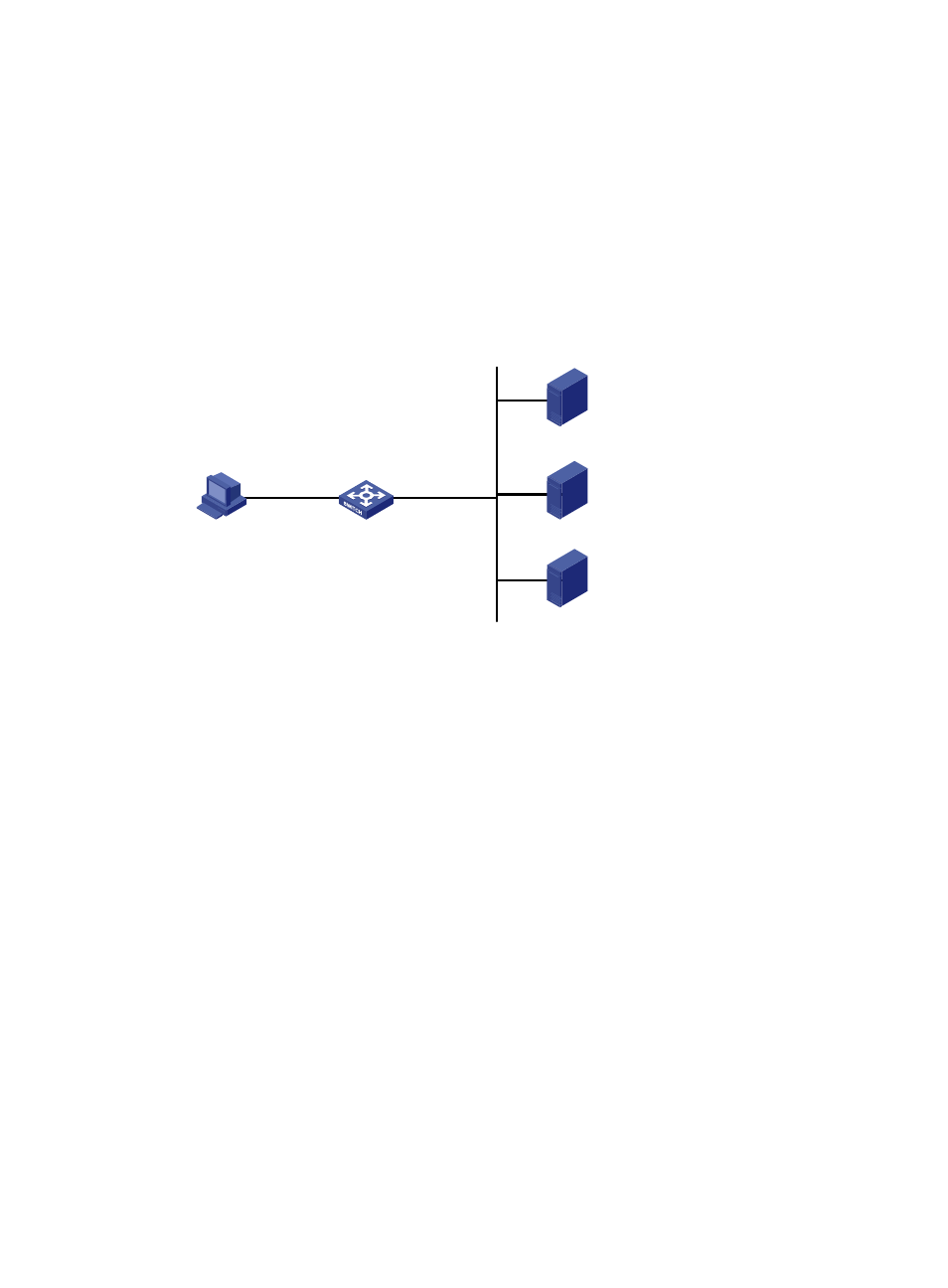
As shown in
, the host is directly connected to the switch (the access device). The host obtains
an IP address through the DHCP server. A portal server serves as both a portal authentication server and
a portal Web server. A RADIUS server serves as the authentication/accounting server.
Configure re-DHCP portal authentication. Before passing the authentication, the host is assigned a
private IP address. After passing the authentication, the host gets a public IP address and can access
Internet resources.
Figure 47 Network diagram
Configuration prerequisites and guidelines
•
Configure IP addresses for the switch and servers as shown in
and make sure the host,
switch, and servers can reach each other.
•
Configure the RADIUS server properly to provide authentication and accounting functions.
•
For re-DHCP portal authentication, configure a public address pool (20.20.20.0/24) and a private
address pool (10.0.0.0/24) on the DHCP server. (Details not shown.)
•
For re-DHCP portal authentication:
{
The switch must be configured as a DHCP relay agent.
{
The portal-enabled interface must be configured with a primary IP address (a public IP address)
and a secondary IP address (a private IP address).
For information about DHCP relay agent configuration, see Layer 3—IP Services Configuration
Guide.
•
Make sure the IP address of the portal device added on the portal server is the public IP address
(20.20.20.1) of the switch's interface connecting the host. The private IP address range for the IP
address group associated with the portal device is the private subnet 10.0.0.0/24 where the host
resides. The public IP address range for the IP address group is the public subnet 20.20.20.0/24.
Configuration procedure
Perform the following tasks on the switch.
1.
Configure a RADIUS scheme:
# Create a RADIUS scheme named rs1 and enter its view.
192.168.0.111/24
192.168.0.113/24
192.168.0.112/24
Switch
Host
automatically obtains
an IP address
Vlan-int100
20.20.20.1/24
10.0.0.1/24 sub
Vlan-int2
192.168.0.100/24
Portal Server
RADIUS server
DHCP server
